Installation Instructions Zip HydroTap G4 ® Filtered Chilled drinking water for residential kitchens and tea rooms. Affix Model Number Label Here 802261 802261 - Residential HT- CO Installation Instructions - March 2016 - V3.
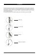
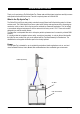
Tap options The HydroTap appliance series offers a range of interchangeable taps to suit the customer’s needs (See options below). For ease of installation, it is recommended to fit the tap before installing the undersink unit. The installation procedure for each of the taps is detailed in a separate tap installation instruction book No. 803341, supplied with the tap. For all operational features of the HydroTap, please refer to the Chilled User manual No.802262.
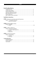
Index HydroTap Specifications Installation check list .................................................................................................................... 4 General Product Features ............................................................................................................ 5 Important Safety Instructions ....................................................................................................... 6 Warnings and Regulatory Information...............................
Installation checklist Before Installation: A. Read the instructions and check if there is adequate space to mount all of the components. B. Note: Not all fittings are supplied with the appliance kit. Isolation valves are not supplied. C. Check the mains water pressure is between 172 - 700kPa D. Check the water quality to determine if extra filtration will be required. E. Check the appliance rating plate and ensure correct power is available for the appliance. F.
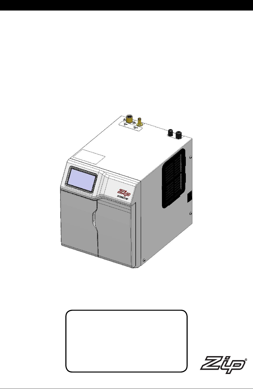
General Product Features Thank you for purchasing a Zip Chilled HydroTap. Please read and follow these instructions carefully to ensure safe operation and trouble free service. If service is required, please call 1800 460 222 What is the Zip HydroTap ? The Chilled Zip HydroTap is electronically controlled to supply filtered and Chilled drinking water for kitchens and tea rooms.
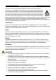
Important Safety Instructions This manual contains important safety, installation instructions for the Zip HydroTap G4. This appliance is not intended for use by persons (including children) with reduced physical, sensory or mental capabilities, or lack of experience and knowledge, unless they have been given supervision or instruction concerning use of the appliance by a person responsible for their safety. Children should be supervised to ensure that they do not play with the appliance.
Major components and accessories Parts supplied Description Accessories Description HydroTaps with hoses.
Technical Specifications Residential models: C = Chilled filtered CHA = Chilled Hot and Ambient D = Disabled lever controls, (Order as an option for Classic Tap ) Note: the standard Glass measurement =200ml Product covered by these instruction: Boost (10A) GPO's Required Power Rating (kW) Unit Dimensions W x D x H (mm) **Dry Weight (Kg) 1x10A 0.
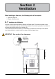
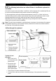
Section 2 Ventilation When installing air flow ducts, the following tools will be required: • Jigsaw and 12mm Drill • Keyhole or Wall Board saw. 2.1 Ventilation for All Models Proper air circulation must be provided for all Boiling and Chilled models. The system will operate correctly only if the recommended air gaps are achieved during Installation. The minimum requirement is for a 50mm air gap either side and 300mm above of the undersink unit.
Ventilation 2.2 The following instructions are critical if there is insufficient cupboard air circulation. If the air flow, using the silicon door buffers, is insufficient, it will be necessary to fit a standard HydroTap vent kit, which ensures heat dissipation through natural convection via installed vents. For high use applications, where the cupboard space temperature is near 35°C, or higher, the inlet vent (See Item B below) and silicon buffers, need to be fitted.
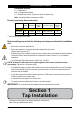
Section 3 Undersink Unit Installation 3.1 Hose and tube fitting. (Do not overtighten) - Remove all caps from the top of the undersink unit ; - Install the mains water braided hoses to the undersink unit before locating the unit in place. - Fit the foam insulation to the Blue tube after trimming to length BRAIDED BLUE MAINS IN CHILLED OUTLET USB Note: All silicon tubes must be cut to size. They must have a constant fall back to the unit. POWER CORD 3.
Installation 3.3 - Celsius - CHA BRAIDED BLUE MAINS IN CHILLED OUTLET USB Note: All silicon tubes must be cut to size. They must have a constant fall back to the unit.
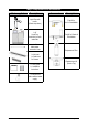
Section 4 Commissioning • Turn the power ON at the GPO and at the side of the undersink unit • Turn ON the water and check for any leaks. • At first commissioning, the screen will prompt you to select a language. • Familiarise yourself with the operation of the Tap, in preparation for use (See User Guide) • Follow the Installation instructions below (and review Section C of the User Guide).
Trouble Shooting System Fault Message Power Board Fault Interface Fault Level Board Fault Condenser Screen Blocked Water leak, Isolate Mains Compressor OverRun Water Supply Failure Cold Sensor Open Cold Sensor Closed Flood Sensor Open Condenser Sensor Closed Condenser Sensor Open Compr.
End of Life Disposal In order to help preserve our environment we ask that you dispose of this product correctly. Please contact your local city council for collection centre details. 802261 - Residential HT- CO Installation Instructions - March 2016 - V3.
Contact Details Head Office Zip Heaters (Aust) Pty. Ltd. ABN: 46 000 578 727 67 Allingham Street Condell Park NSW 2200 Postal: Locked Bag 80 Bankstown 1885 Australia Website: www.zipwater.com Facsimile: (02) 9796 3858 Telephone: (02) 9796 3100 Free Call: 1 800 638 633 As Zip policy is one of continuous product improvement, changes to specifications may be made without prior notice. Images in this booklet have been modified and may not be true representations of the finished goods.