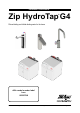
Installation instructions Zip HydroTap G4 ® Filtered boiling and chilled drinking water for the home. Affix model number label here 802257UK 802257UK - G4 Boiling (& ambient) residential installation instructions - Aug 2015 - V2.
Tap options The G4 series offers a range of interchangeable taps to suit the customer's needs Classic HydroTap®G4 range These standalone taps are directly compatible with the G4 Command-CentreTM. Arc / Cube range Elite range The mixer tap range may be used in conjunction with any of the above to provide mixed hot and cold water for sanitary use. Mixer range Page 2 of 32 802257K - G4 Boiling (& ambient) residential installation instructions - Aug 2015 - V2.
Index HydroTap®G4 specifications Installation check list..................................................................................................................... 4 General product features.............................................................................................................. 5 Important safety instructions......................................................................................................... 6 Warnings and regulatory information..........................
Installation checklist Before installation • Read the instructions and check if there is adequate space to install all of the components. • Note Not all fittings are supplied with the appliance kit. Isolation valves are not supplied. • Check the mains water pressure is within min / max requirements (see page 9). • Check the water quality to determine if extra filtration will be required. • Note This product must be fitted to a potable water supply.
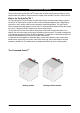
General product features Thank you for purchasing a Zip HydroTap®G4. Please read and follow these instructions carefully to ensure safe and trouble free operation. If help and advice is required, please call 0845 6 005 005 or 0345 6 005 005. What is the Zip HydroTap®G4 ? This Zip HydroTap®G4 is an electronically controlled, filtered, boiling and ambient water drinking system for the kitchen.
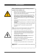
Important safety instructions This manual contains important safety and installation instructions for the Zip HydroTap®G4. Please read all warnings, installation requirements and installation instructions before installing any Zip HydroTap®G4. This system must be installed in accordance with water supply byelaws, current IEE regulations and relevant local authority byelaws.
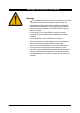
Warnings and regulatory information Warnings • • • • • • • • • The Zip HydroTap®G4 must be earthed. The resistance of the earth connection from each exposed metal part must be less than 1Ω. All installation and service work must be completed by trained and suitably qualified tradespeople. Faulty operation due to unqualified persons working on this product, or any other Zip product may void warranty coverage.
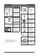
Major components and accessories Parts supplied Description Tap options 1x HydroTap®G4 Classic Elite or Arc / Cube 1 x Mixer tap Classic, Arc or Cube Command-CentreTM and components 1x Command-CentreTM with air and water filters 1 x Mains water connection hose QUICK START GUIDE Note: This quick start guide must be read in conjunction with the main installation and user instructions • • • • STEP 1- Prepare and fit the Taps HydroTap Tap Sufficient space in the cupboard to install all of the undersink un
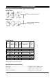
Technical specifications Commercial Boiling Chilled HydroTap®G4 range HydroTap®s Boiling, (ambient) and filtered. Elite Classic + Arc / Cube Mixer taps Boiling, (ambient), filtered and mixed hot & cold. Classic Arc Cube Specifications Boost (10A) 13A sockets required Power Boost Rating Rating (kW) (kW) 230V 230V Unit Dimensions W x D x H (mm) with air duct Boiling, ambient and filtered, without booster no 1x13A 1.43 N/A 280 x 313 x 335 Boiling and filtered, without booster no 1x13A 1.
Before installation Before installation ensure that the following have been provided at the installation site • Review of all the technical specifications. • Ensure the under counter cupboard floor can support the product weight when full of water (allow an extra 3-4kg when full). • Sufficient space in the cupboard to install the Command-CentreTM and other components in accordance with these installation instructions. See technical specification, page 9 for dimensions.
Section 1 Tap installation Special tools required In addition to normal tools, the following will be required. For the HydroTap®G4 and mixer taps. • 35mm diameter sheet metal hole punch for sink tops (not supplied). • 35mm diameter hole saw for worktops (not supplied). • Nut runner tube spanner (supplied) for fixing the tap assembly. When installing a font, the following will be required • Classic and Elite, 108mm diameter sheet metal or hole saw to suit surface being cut.
HydroTap®G4 Classic & Elite - tap installation (See page 24 to 27 for Command-CentreTM connections). min. 300mm 1.1 All thread rod Stainless steel spacer 335mm Spider clamp Clearance envelope 535mm Black plastic spacer Nut 1.2 Apply a light smearing of silicon sealant on the underside of the spacer to ensure a watertight fit. Cut a Ø35mm hole in the work / sink top. Ø35mm Note Make sure the tap location will allow the tap spout to drain into the sink.
Installation instructions 1.3 1.4 Black plastic spacer Fit the stainless steel washer, spider clamp, and nut. Ø35mm hole Stainless steel washer Spider clamp Nut Note feed each of the three tubes and USB cable evenly in between the legs of the spider clamp during installation. Pass all the hoses, tubes and USB cable through the 35mm hole. 1.
HydroTap®G4 Arc & Cube - tap installation (See page 24 to 27 for Command-CentreTM connections). The HydroTap Arc/Cube has a spout that may be fixed in one of 6 angular positions (depending on the position of the rotary control) and fixed in one of two height positions. The spout is fixed and does not swivel. To reduce the risk of scalding, Position A should not be selected with any of the boiling water units*. (See fig. 1.8). 1.
Installation instructions 1.7 Height adjustment (fixed position options) 50mm 1.8 Angular adjustment (fixed position options) Right hand control Left hand control *A B C 1.9 Mounting (See hole positioning, page 11 ) Cut a Ø35mm hole in the work / sink top. Ø35mm Note Make sure the tap location will allow the tap spout to drain into the sink.
Mixer tap installation (See page 26 and 27 for Command-CentreTM connections). Upper rubber washer Braided hose x 3 535mm Lower rubber washer Washer Clearance envelope Nut 335mm min. 300mm 1.10 1.11 Cut a Ø35mm hole in the work / sink top. Ø35mm Upper rubber washer Note Make sure the tap location will allow the tap spout to drain into the sink. Note The mixer tap requires a Restrictaflow valve, supplied, to be fitted in the cold water supply line, from the isolation valve T-piece, to the mixer tap.
Section 2 Ventilation 2.1 Ventilation for all models • • The clearance envelope dimensions stated in the specification sheets and installation instructions must be observed. Adequate ventilation must be provided to ensure that the cupboard space temperature does not exceed 350C. 2.2 Preferred arrangement • 4mm door buffers (at the four corners of each door) supplied with the Command-CentreTM should be used to provide adequate ventilation in normal usage, see illustration below.
Installation instructions 2.3 Alternative arrangement • For high use applications where the cupboard space temperature is near 350C or higher, a vent kit (SP91545) can be used to provide further ventilation by convection. When installing air flow vents , the following tools will be required • • Jigsaw and drill. Keyhole or wall board saw. Note The vent kit has to be installed in a way that allows air to be drawn in from the bottom of the cupboard and expelled through the top of the cupboard.
Section 3 Booster system 3.1 Product description The booster system is a compact electronically controlled auxiliary water heater. It is intended to provide pre-heating of water before it enters the Zip HydroTap®G4 boiling tank. The booster is used to present approx. 55°C hot water for sanitary use to a secondary outlet with additional “Vented Mixer” kit. Note 1 Water connection blue cap - water in red cap - water out. The braided hoses cannot be lengthened. Note 2 The electrical cable length is 0.6m.
Booster installation 3.2 Installation procedure Site requirements • Booster must only be installed in a frost-free area. Never expose booster to frost. • The booster is designed for wall mounted installation and must be installed with water connectors facing upwards. • The booster is protected against water ingress to class IP 25. • The 500mm braided hoses supplied with the booster cannot be lengthened. • The 90° elbow hose ends should be fitted to the inlet and outlet connections on top of the booster.
Booster system Note 1 This appliance is intended for use with the Zip HydroTap®G4 Command-CentreTM Note 2 Water connections must be pointing vertically upwards. Note 3 The booster unit should be installed as close as possible to the Zip HydroTap®G4 as the 500mm connection hoses cannot be lengthened. 3.4 Braided hose connections • • The cold water inlet (blue cap) and hot water outlet (red cap) are marked on the rating plate.
Filter / softener installation An external filter / softener may be fitted to reduce the incidence of scale build up in the hot tank or may be supplied at the customer’s request. (Scale filter head fitting kit order code ZT200G4). 3.5 Mounting the filter head • Choose a suitable location, (cupboard back or side wall) within the reach of the braided hoses. • Mount the filter head bracket in an upright position, using the screws supplied in the ZT200G4 kit.
Section 4 Command-CentreTM installation 4.1 External bypass valve The diverter bypass valve allows the user to choose to have the boiling feed water bypass the internal filter and only be filtered by the external filtration. This diverter valve is located at the rear panel of the Command-CentreTM, see the diagram below. Check the table below to determine which filter bypass position you need for your product.
Installation instructions 4.3 Hydrotap®G4 boiling models (for Arc / Cube, also refer to the tube kit assembly instructions supplied with the tap head). MAINS IN Booster option Arc / Cube RED MIXER OUT MIXER IN BOILING OUT CLEAR Classic BRAIDED Elite BYPASS VENT IN BYPASS OUT USB POWER CABLE Note All silicon tubes / plastic pipes must be cut to size. They must have a constant fall back to the Command-CentreTM Note Ambient mains water braided hose length is 750mm.
Installation instructions 4.4 Hydrotap®G4 boiling ambient models (for Arc / Cube, also refer to the tube kit assembly instructions supplied with the tap head). Booster option Arc / Cube MAINS IN MIXER BOILING BYPASS VENT OUT IN IN BLUE RED MIXER OUT CLEAR Classic BRAIDED Elite BYPASS USB AMBI- POWER ENT CABLE OUT OUT Note All silicon tubes / plastic pipes must be cut to size. They must have a constant fall back to the Command-CentreTM Note Ambient mains water braided hose length is 750mm.
Installation instructions 4.5 Hydrotap®G4 boiling and mixer tap combinations (for Arc / Cube, also refer to the tube kit assembly instructions supplied with the tap head). + MAINS IN Classic Arc / Cube Cube Booster option RED HydroTap Mixer Connections MIXER OUT Arc CLEAR Classic BRAIDED Elite MIXER BOILING BYPASS VENT OUT IN IN BYPASS OUT USB POWER CABLE Note Ambient mains water braided hose length is 750mm. Electrical power cable length is 1800mm.
Installation instructions 4.6 Hydrotap®G4 boiling ambient and mixer tap combinations (for Arc / Cube, also refer to the tube kit assembly instructions supplied with the tap head). + Elite Classic Classic Arc / Cube Arc Cube MAINS IN MIXER OUT MIXER BOILING BYPASS OUT IN IN VENT BLUE CLEAR HydroTap Mixer Connections RED BRAIDED Booster option BYPASS USB AMBI- POWER ENT CABLE OUT OUT Note Ambient mains water braided hose length is 750mm. Electrical power cable length is 1800mm.
Section 5 Commissioning The HydroTap®G4 is now ready to be commissioned. • Turn the power and water on and check for any leaks. • If fitted, ensure the booster is turned off. (The booster is commissioned later, see page 29). • Familiarise yourself with the operation of the tap, in preparation for use, see the user guide. • Follow the installation instructions below (and read section C of the user guide).
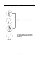
Commissioning 5.4 Boiling calibration (boiling models) • Press the [Calibrate] button and the system will start the boiling calibration procedure. This will take approx. 5 to 6 minutes. 5.5 To enable a booster, when installed. Press the [MENU] button for main menu. Press the [Install] button. Zip Boiling Press the [Boost] button. In the next screen, select [YES] to enable the booster. Before connecting the power to the booster, water must be run through for a min. of 30 seconds to purge.
Trouble shooting System fault message Power Board Fault Interface Fault Level Board Fault Water leak, Isolate Mains Water Supply Failure Hot Sensor Open Hot Sensor Closed Flood Sensor Open Heater Fuse / Driver Fault Heater Driver Fault Hot Sensor Degraded A DC Pump is faulty Steam too Cool Steam Sensor Open Steam Sensor Closed Over Steamed Hot Tank Over filled Hot Tank Under filled Boil Dry Protection Flash Memory corrupted Flow Sensor Fault Possible cause Electrical disruption Internal fault Internal fau
End of life disposal The use of this crossed out wheeled bin logo indicates that this product needs to be disposed of separately to any other household waste. Within each of the European Union member countries, provisions have been made for collection and recycling of unwanted electrical and electronic equipment. In order to help preserve our environment we ask that you dispose of this product correctly. Please contact Zip Customer Service on 0845 6 005 005 or 0345 6 005 005 for advice.
Contact Details Head Office Zip Heaters (UK) Ltd. 14 Bertie Ward Way Dereham Norfolk NR19 1TE Website: www.zipheaters.co.uk Email: sales@zipheaters.co.uk Facsimile: 01362 692 448 Telephone: 0845 6 005 005 Mobile: 0345 6 005 005 The standard cup referred to in this publication is 167 ml (6 fl oz). The standard glass is 200 ml (7 fl oz). The terms “Zip” and “HydroTap” are registered trade marks of Zip Heaters (Aust) Pty Ltd.