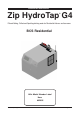
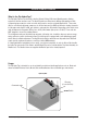
Installation Instructions Zip HydroTap G4 ® Filtered Boiling, Chilled and Sparkling drinking water for Residential kitchens and tea rooms. BCS Residential Affix Model Number Label Here 802005 802005 - Sparkling HT-BCS Residential- Installation Instructions - 09.2016 - v3.
Tap options The HydroTap applaince series offers a range of interchangeable taps to suit the customer’s needs (See options below). For ease of installation, it is recommended to fit the tap before installing the undersink unit. The installation procedure for each of the taps is detailed in a separate tap installation instruction book No. 803341, supplied with the tap. For all operational features of the HydroTap, please refer to the BCS User manual No.802006.
Index HydroTap Specifications Installation check list .................................................................................................................... 4 General Product Features ............................................................................................................ 5 Important Safety Instructions ....................................................................................................... 6 Warnings and Regulatory Information...............................
Installation checklist Thank you for purchasing a Zip HydroTap. Please read and follow these instructions carefully to ensure safe and trouble free service. If service is required, please call 1800 638 633 Before Installation: A. Read the instructions and check if there is adequate space to mount all of the components. B. Note: Not all fittings are supplied with the appliance kit. Isolation valves and special tools are not supplied (See Technical Specifications for details). C.
General Product Features What is the Zip HydroTap ? The Zip HydroTaps are electronically controlled, filtered, Boiling, Chilled and Sparkling water, drinking systems for kitchens and tea rooms. The HydroTap units are under bench drinking water appliances with a dispensing tap mounted on a sink or bench, which may be used for residential applications.
Important Safety Instructions This manual contains important safety, Installation instructions for the Zip HydroTap G4. Safety This appliance is not intended for use by persons (including children) with reduced physical, sensory or mental capabilities, or lack of experience and knowledge, unless they have been given supervision or instruction concerning use of the appliance by a person responsible for their safety. Children should be supervised to ensure that they do not play with the appliance.
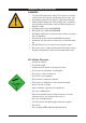
Important Safety Instructions WARNINGS 1. 2. 3. 4. 5. 6. 7. 8. 9. The Zip HydroTap unit must be earthed. The resistance of the earth connection from each exposed metal part must be less than 1 ohm. All Installation and service work must be completed by trained and suitably qualified Tradespeople. Faulty operation due to unqualified persons working on this product, or any other Zip product may void warranty coverage. All Plumbing must comply with AS/NZS3500.
Major components and accessories Parts supplied Description 1 off 4 HydroTaps with hoses (Classic tap shown) 1 off HydroTap Undersink Unit with air and water filters 1 off Mains water connection hose Vent Kit 1 x Inlet vent 1 x Outlet vent 9 x Screws User Manual Quick start guide Accessories Description Softener and head assembly Font Kit for Arc & Cube Models Font Kit for Classic & Elite Models Replacement Filter 1 x User guide and 1 x Quick start guide 1 off CO2 gas cylinder & regulator assy.
Technical Specifications Product covered by these instructions: BCS BCSHA BCSHAV D = Boiling Chilled Sparkling, Filtered = Boiling Chilled Sparkling, Hot & Ambient (Mains) = Boiling Chilled Sparkling, Hot & Ambient (Vented) = Disabled lever controls, (Order as an option) NOTE: chilled water will continue to be dispensed after the rated capacity has been used, although this may be at slightly higher temperature.
Before Installation Before installing ensure that the following have been provided at the Installation site: • Review all the technical specifications. • Ensure the underbench can support the product weight when full of water, (allow an extra 5kg when full. ) • Sufficient space in the cupboard to install all of the undersink units in accordance with these Installation Instructions. Refer to technical specification for dimensions. Make allowance for a booster heater and / or water softener if required.
Section 2 Ventilation When installing air flow ducts, the following tools will be required: • Jigsaw and 12mm Drill • Keyhole or Wall Board saw. 2.1 Ventilation for All Models Proper air circulation must be provided for all Boiling and Chilled models. The system will operate correctly only if the recommended air gaps are achieved during Installation. The minimum requirement is for a 50mm air gap either side and 300mm above of the undersink unit.
Ventilation 2.2 The following instructions are critical if there is insufficient cupboard air circulation. If the air flow, using the silicon door buffers, is insufficient, it will be necessary to fit a standard HydroTap vent kit, which ensures heat dissipation through natural convection via installed vents. For high use applications, where the cupboard space temperature is near 35°C, or higher, the inlet vent (See Item B below) and silicon buffers, need to be fitted.
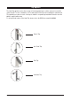
Ventilation Typical Cut out procedure for B D Mark out and cut the air inlet and door outlet holes as shown 2. Ensure the air inlet vent and air outlet vent are positioned at opposite ends of the same cupboard space. 3. Fit the inlet vent, as shown and secure with 5 screws 4. If required, fit the outlet vent, as shown in the hottest part (top) of the cupboard and secure with 4 screws 1. Air inlet vent B Cutout deatils 802005 - Sparkling HT-BCS Residential- Installation Instructions - 09.2016 - v3.
Section 3 Booster Heater 3.1 Product Description The boost unit is a compact electronically controlled auxillary water heater. It is intended to provide pre heating of water before it enters the Zip HydroTap G4 boiling tank. The Booster is supplied with the BCSHAV model. However, it may be later installed, as an accessory for the BCS model, to increase its delivery. Note1: water connection :Blue marking - water in :Red marking - water out. The braided hoses cannot be lengthened.
Booster Installation 3.2 Installation Procedure Site requirements • Appliance must only be installed in a frost-free area. Never expose appliance to frost. • The Appliance is designed for wall mounted Installation and must to be installed with water connectors facing upwards. • The appliance complies with protection class IP 25. • The 300mm braided hoses supplied with the unit cannot be lengthened. • The 90° elbow hose ends, should be fitted to the inlet and outlet connections on top of the Booster.
Booster System NOTE1: This appliance is intended for use with the Zip HydroTap under sink unit. NOTE2: Water connections must be pointing vertically upwards. NOTE3: The booster unit should be installed as close as possible to the Zip HydroTap Unit as the 400mm connection hoses cannot be lengthened. 3.4 Braided hose connections The cold water inlet (blue) and hot water outlet (red) are marked on the rating plate.
Section 4 CO2 Cylinder WARNING: This cylinder mus be installed in an open plan area or in an enclosed room, with a volume no less than 20m3. If more than 1 gas cylinder containing CO2 is present within the same location, the recommended ventilated area should be in proportion to the number of gas cylinders stored in that location. A ventilated area is a non-enclosed area which could include the kitchen, living room etc. See gas bottle and MSDS sheet for a complete list of warnings. (See: www.zipindustries.
CO2 Connections & Leak Testing 4.4 Test for gas leaks: Using soapy water perform a leak test. Apply the soapy water to the gas connections using a sponge. If any bubbles appear and grow, there is a gas leak at the connection. Clean away the soapy residue and tighten or refit the leaking connection. Make sure the regulator is turned off when tightening or refitting the leaking connection. Refit the gas bottle to the Hook-and-loop strap and secure the bottle in an upright position.
Section 5 Undersink Unit Installation Note: Before you install a unit, determine whether a water softener or an external filter is required. 5.1 External Bypass Valve The diverter bypass valve allows the user to choose to have the boiling feed water bypass the internal filter and only be filtered by the external filtration. This diverter valve is located at the rear panel of the Zip HydroTap undersink unit on the filter door side, see the image below.
Installation Instructions BRAIDED WHITE BLUE RED CLEAR Model BCS BRAIDED 5.3 MAINS MIXER MIXER BOILING BYPASS VENT BYPASS CHILLED CO2 OUTLET IN OUT IN OUT IN OUT IN SPARKLING OUTLET Max. 1000mm Min. 50 mm side Clearance 339 mm Note: All silicon tubes must be cut to size. They must have a constant fall back to the unit.
Installation Instructions BRAIDED WHITE BLUE CLEAR RED Model BCSHA All-In-One (Mains) BRAIDED 5.4 MAINS MIXER MIXER BOILING BYPASS VENT BYPASS CHILLED CO2 OUTLET IN OUT IN OUT IN OUT IN SPARKLING OUTLET Note: All silicon tubes must be cut to size. They must have a constant fall back to the unit.
Installation Instructions 5.5 Note: All silicon tubes must be cut to size. They must have a constant fall back to the unit.
Section 6 Commissioning The HydroTap is now ready to be commissioned. • Turn ON the water and gas and check for any leaks. • Turn the power ON at the GPO and at the side of the undersink unit • If fitted, ensure the Booster is turned OFF. (The Booster is commissioned, later, at section 7.4) • Familiarise yourself with the operation of the Tap, in preparation for use (See User Guide) • Follow the Installation instructions below (and review Section C of the User Guide).
Commissioning OPEN Position ON Stop cock operation CLOSED Position OFF 6.3 - Boiling Calibration (Boiling models) • Press the calibration button and the system will commence the Boiling calibration procedure. This will take approx 5-6 minutes. 6.4 - Booster • Upon completion, a Booster reminder screen will appear and allow you to return home by pressing the [Home] button.
Commissioning To enabled when a Booster unit is installed. 1. Press the [MENU] button for main menu. 2. Press the [Install] button. 3. Press the [Booster] button. 4. In the next screen, select YES to enable the Booster. 5. Water must be run through the Booster for a min of 30 seconds, before the heater will activate. 6. Dispense boiling water for 30secs and check the Booster outlet hose is warm when the boiling water tank is replenishing.
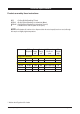
Trouble Shooting System Fault Message Power board fault Interface fault Level board fault Condenser screen blocked Water leak, Isolate mains Compressor over-run Water supply failed Hot sensor Open Hot sensor Closed Cold sensor Open Cold sensor Closed Flood sensor Open Condenser sensor Closed Condenser sensor Open Heater fuse / driver fault Heater driver fault Compressor driver fault Hot sensor degraded Condenser overtemp.
Notes 802005 - Sparkling HT-BCS Residential- Installation Instructions - 09.2016 - v3.
Contact Details Head Office Zip Heaters (Aust) Pty. Ltd. ABN: 46 000 578 727 67 Allingham Street Condell Park NSW 2200 Postal: Locked Bag 80 Bankstown 1885 Australia Website: www.zipwater.com Facsimile: (02) 9796 3858 Telephone: (02) 9796 3100 Free Call: 1 800 638 633 As Zip policy is one of continuous product improvement, changes to specifications may be made without prior notice. Images in this booklet have been modified and may not be true representations of the finished goods.