
Guide

802007 - BCS. CS. Residential Quick Start Guide - 09.2016 - v3.01
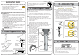
Note: Remove all caps from the top of the undersink unit and Install the mains water
braided hoses to the undersink unit before locating the unit in place..
7 - HydroTap Unit
Note:
-
Mains hose length is 750 mm
- Plug and Cord length is 1800mm
Position the undersink unit according to the hose
and cord lengths supplied
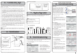
8 - Commissioning
OPEN Position
CLOSED Position
ON
OFF
Stop cock
operation
Have a 10L bucket or similar container (not
supplied) at the ready to hold a quantity of
water that will be ejected while the Filter
Flush Mode is in operation. Open the filter
access door on the front of the HydroTap
and the filter cartridge will be exposed.
Located to the rear RHS of the cartridge is a
flush line, approx 600mm long and the flush
line stop cock. Place the valve end of the
flush line into the 10L bucket or container.
1.
Turn the stop cock ON
2.
Press [Start] button to start filter flush.
3.
Allow at least 10 litres of water to flush through
the filter.
4.
Once the filter flush is finished, Turn the stop
cock OFF then press [Stop] to end filter flush
mode.
Flow Calibration:
1.
Press [Next] and the View screen will show
the Flow calibration mode.
2.
Press the [Start] button and the tank will
first empty then fill. Upon completion the
actual pulse will be displayed. Check this
reading is within the limits
Boiling Calibration:
1.
Press [Next] for the Boiling Calibration screen.
2.
Press the calibration button and the system will
commence the Boiling calibration procedure.
This will take aprox 5-6 minutes.
3.
Upon completion, a Booster reminder screen
will appear and allow you to return home by
pressing the [Home] button.
4.
Check the Date and Time settings (See section
G of the user guide)
To enable the Booster: (when installed)
• Press the [MENU] button for main menu.
• Press the [Install] button.
• Press the [Booster] button.
• In the next screen, press YES to enable the
Booster.
• Turn the Booster ON
• Water must be run through the Booster for
a min of 30 seconds, before the heater will
activate.
• Dispense boiling water for 30 seconds and
check the Booster outlet hose is warm when
the boiling water tank is replenishing.
Note
Note: Failing to make the correct selection for the
“Booster”, will affect product performance.
Filter Flush:
Commissioning the HydroTap
1.
Press the [START] button to
commence the purging process.
2.
Purge for 5 seconds and ensure all
water has stopped flowing through
the tap. (You will hear the CO
2
gas
escaping from the tap).
3.
Press the [Stop] button.
4.
Press [Next] for the filter flush screen
CO
2
Purge:
• Turn on the water and gas to check for any leaks before turning on the power
(Check the switch on the side of the unit is ON).
• The system will promp you to select a language before continuing with the
filter flush procedure
8 - Commissioning
6 - Ventilation
Note: For alternative options, refer to section 2 of the main instructions
5 - 1.0 KG CO
2
Cyl.
Cool air IN
Warm air
OUT
1.
Drill four pilot holes 12mm
dia.
2.
Finish the cutout using
a jig saw and keyhole or
Wall Board saw
1.
Drill fo
ur
p
ilot hol
es
12m
m
Cutout details
BCS / BCSHAV Model
Air inlet vent position
Air inlet vent cutout details
This cylinder must be installed in an open plan area or in an enclosed room, with a
volume no less than 20 m
3
. See details on the gas bottle and in the MSDS sheet for
a complete list of warnings.
1.
Secure the gas bottle supplied to a suitable wall, within 1 metre of the unit,
in an upright position. This is done by screwing the metal plate holding the
Hook-and-loop strap to a cupboard wall, 200mm above the floor or base of the
cupboard. Make sure the gas bottle can stand before securing to the wall. Due
to regulatory requirements the gas bottle must be stored securely and in an
upright position.
2.
Make sure the regulator knob is turned fully anti-clockwise to the end-stop
before fitting. Remove the gas bottle from the wall to fit the regulator. Be aware
that some CO
2
may be discharged from the connection during assembly. To
avoid excess gas leakage, promptly screw the regulator on to the bottle.
3.
Connect the braided gas hose to the top of the undersink unit via the John
Guest fitting marked ‘Gas IN’ Then connect the threaded end to the regulator,
taking care not to lose the plastic olive located inside the threaded nut. When
commissioning, turn the gas ON by rotating the regulator knob clockwise and
adjust to 2.7-3.0 bar (270-300kPa). The arrow should sit in the green section of
the regulator gauge; it should not fall in the red or yellow sections.
4.
When commissioning, use soapy water to perform a leak test. Apply the soapy
water to the gas connections using a sponge. If any bubbles appear and grow,
there is a gas leak at the connection. Clean away the soapy residue and tighten
or refit the leaking connection. Make sure the regulator is turned off when
tightening or refitting the leaking connection.
5.
Refit the gas bottle to the Hook-and-loop strap and secure the bottle in an
upright position.
NOTE:
Care must be taken when working with high pressure carbon dioxide,
and in no cases should the normal operating pressure of 2.7-3.0 bar (270-300kPa)
be exceeded.
RED
CLEAR
BLUE
BRAIDED
WHITE
GAS IN
POWER
CORD
USB
CHILLED
OUTLET
MAINS IN
MIXER OUT
MIXER IN BOILING
OUT
BYPASS IN VENT BYPASS
OUT
SPARKLING
OUTLET
CO2
GAS
Note:
Insulate the
Blue and
the White
tubes after
Trimming to
length
Booster
Booster
HydroTap
HydroTap
Mixer
Mixer
Connections
Connections