
Guide

802263 - Res HT CO - Quick Start Guide - July 2015 - V2.00
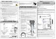
STEP 3- Install the undersink unit
HydroTap Unit
Side outlet vent (Option 2)
Door outlet
vent
(Option 1)
Front inlet vent
Cool Air IN
Warm Air OUT
Ventilation
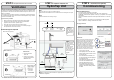
STEP 2- Cut cupboard holes and fit the air vent ducts
POWER
CORD
USBCHILLED
OUTLET
MAINS
IN
BLUEBRAIDED
Min
50 mm
280 mm
Max
1750 mm
Max
400 mm
Note:
Remove all caps from the top of the undersink unit and
Install the mains water braided hoses to the undersink unit before locating the unit in place.
Note:
Insulate the Blue tube after Trimming to length
Typical Cut out procedure
1.
Mark out and cut the air inlet and door outlet holes as shown
2.
Ensure the air inlet vent and air outlet vent are positioned at
opposite ends of the same cupboard space.
3.
Fit the inlet vent, as shown and secure with 5 screws
4.
If required, fit the outlet vent, as shown in the hottest part (top) of
the cupboard and secure with 4 screws
Airflow through the cupboard
Cutout details
Air inlet vent
B
D
Door outlet vent
1.
Drill four pilot holes
12mm dia.
2.
Finish the cutout using
a jig saw and keyhole or
Wall Board saw
Note: The vent kit has to be installed in a way that allows air to be drawn in from
the bottom of the cupboard and expelled through the top of the cupboard. There-
fore placement of the outlet vent should be towards the top of the door or on the
side of the cupboard.
If the air flow, using the silicon door buffers, is insufficient, it will be necessary to
fit a standard HydroTap vent kit, which ensures heat dissipation through natural
convection via installed vents.
Cutout details
D
B
STEP 4 - Commission the HydroTap
Commissioning
1.
Turn the stop cock ON
2.
Press [Start] button to start filter flush.
3.
Allow at least 10 litres of water to flush
through the filter.
4.
Once the filter flush is finished, Turn
the stop cock OFF then press [Stop] to
end filter flush mode.
5.
Press [Next] and the View screen will
show the Flow calibration mode.
6.
Press the [Start] button and the
tank will first empty then fill. Upon
completion the actual pulse will be
displayed. Check this reading is within
the limits
OPEN Position
CLOSED Position
ON
OFF
Stop cock
operation
Have a 10L bucket or similar container (not
supplied) at the ready to hold a quantity of
water that will be ejected while the Filter
Flush Mode is in operation. Open the filter
access door on the front of the HydroTap
and the filter cartridge will be exposed.
Located to the rear RHS of the cartridge is a
flush line, approx 600mm long and the flush
line stop cock. Place the valve end of the
flush line into the 10L bucket or container.
Filter Flush:
Before Commissioning:
• Turn ON the water and check for any leaks.
• Turn the power ON at the GPO and at the side of the undersink unit
• Familiarise yourself with the operation of the Tap, in preparation for use (See
User Guide)
• Follow the Installation instructions below (and review Section C of the User
Guide).
• After commissioning, the system may be customised by selecting further
options in Section G - Settings, within the User Guide.
Note:
-
Mains hose length
is 750mm and the
Plug and Cord length
is 1800mm
Position the under
sink unit close to
the outlet tap, within
reach of the hose
and cord lengths
supplied.
Note: The tube lengths are matched to the pumps performance and therefore
CANNOT be lengthened
Note: All
silicon tubes
must be cut to
size. They must
have a constant
fall back to the
unit.
Language selection: