
Guide

802255 - Zip BC, BCHA, AIO, Quick Start Guide - June 2015 - V2.00
Booster Heater
STEP 3- Install the Booster heater (if required)
STEP 4- Install the undersink unit
HydroTap Unit
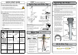
STEP 2- Cut cupboard holes and fit the air vent ducts
Ventilation
Note: For alternative solutions, refer to section 2 of the main instructions
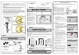
STEP 5- Commission the HydroTap
Commissioning
mount base
Horizontally
Cool air
IN
Warm air OUT
Normal air grille see
details in the next column
B
D
217
65
1.
Drill two pilot holes
12mm dia.
2.
Finish the cutout
using a jig saw
D - Door Vent cut out
B - Inlet grille cut out
details
Note: All
silicon tubes
must be cut
to size. They
must have a
constant fall
back to the
unit.
RED
CLEAR
BLUE
BRAIDED
POWER
CORD
USB
MAINS
IN
MIXER
OUT
MIXER
IN
BOILING
OUT
BYPASS
IN
VENT
BYPASS
OUT
CHILLED
OUT
Note:
Insulate the
Blue and
the White
tubes after
Trimming to
length
Vented braided hose positions
BLUE to
Mixer IN
WHITE
Mains IN
RED from
Mixer OUT
Mains braided hose positions
HOT IN
from HWS
Underside view
BLUE
Mains IN
RED
• Fit the seal ring to the base of the tap and apply a light smear of silicone sealant to
ensure a watertight seal
• Mount the tap on top of the cut out hole after passing the usb cable and tubes through
the 50mm hole
• Thread the cable and silicon tubes through the circular clamp block (Check the tube
colour matches with the coloured dots on the clamp block). (See below)
• Clamp the assembly in position using the threaded nut and clamp block
• Working from inside the cupboard, attach the braided hoses to the tube extensions
(ensure the seals on the end of the hoses are lubricated). Check the correct position
for Hot and Cold connections by matching the colours on the braided hoses with the
coloured markings on the copper extension tubes. (See below)
• Test for leaks after all the connections have been secured.
CLAMP
BLOCK
Braided
hoses
Extension
tubes
Typical Vented assembly
Note: Mains hose length is 750mm and the Plug and Cord length is 1800mm
Position the under sink unit close to the outlet tap, within reach of the hose and cord
lengths supplied.
Ensure their is at least an unobstructed 50mm air gap on both sides of the undersink unit
.
Note:
The tube lengths are matched to the pumps performance and therefore CANNOT
be lengthened.
For other configurations, see the main installation instructions
Note 1: water connection:
Blue marking - water in;
Red marking - water out.
The tubes and hoses cannot be
lengthened.
Note 2: Position the booster
according to the flexible hose
and cable lengths supplied.
Keep the Booster as close as
possible to the undersink unit
inlet/ outlet fittings.
Note 3: Ensure the Booster
heater is mounted in an
upright position (as shown) with
a horizontal base.
Note 4: For mounting details,
refer to section 2 of the main
instructions
Boiling Water
03:01 PM, TUE 12, Feb 2013
Boiling Chilled
To start
press
Calibrate
button
Ca
Calibrate
Steam Vent
97.5
53.0
EL
OPEN Position
CLOSED Position
ON
OFF
Stop cock
operation
If a BOOSTER is installed,
enable in < INSTALL > Menu
03:01 PM, TUE 12, Feb 2013
Boiling Chilled
HOME
Prepare filter flush as per instructions
and press START
03:01 PM, TUE 12, Feb 2013
Boiling Chilled
START
STOP
NEXT
To calibrate, touch START button
NEXT
03:01 PM, TUE 12, Feb 2013
Boiling Chilled
START
Empty / Filling
Pulses/L (360 - 440)
Have a 10L bucket or similar container (not
supplied) at the ready to hold a quantity of
water that will be ejected while the Filter
Flush Mode is in operation. Open the filter
access door on the front of the HydroTap
and the filter cartridge will be exposed.
Located to the rear RHS of the cartridge is a
flush line, approx 600mm long and the flush
line stop cock. Place the valve end of the
flush line into the 10L bucket or container.
1.
Turn the stop cock ON
2.
Press [Start] button to start filter flush.
3.
Allow at least 10 litres of water to flush
through the filter.
4.
Once the filter flush is finished, Turn the stop
cock OFF then press [Stop] to end filter flush
mode.
Flow Calibration:
1.
Press [Next] and the View screen will
show the Flow calibration mode.
2.
Press the [Start] button and the tank will
first empty then fill. Upon completion the
actual pulse will be displayed. Check this
reading is within the limits
Boiling Calibration:
1.
Press [Next] for the Boiling Calibration
screen.
2.
Press the calibration button and the system
will commence the Boiling calibration
procedure. This will take aprox 5-6 minutes.
3.
Upon completion, a Booster reminder screen
will appear and allow you to return home by
pressing the [Home] button.
4.
Check the Date and Time settings (See
section G of the user guide)
To enable the Booster: (when installed)
• Press the [MENU] button for main menu.
• Press the [Install] button.
• Press the [Booster] button.
• In the next screen, press YES to enable the
Booster.
• Turn the Booster ON
• Water must be run through the Booster for
a min of 30 seconds, before the heater will
activate.
• Dispense boiling water for 30 seconds and
check the Booster outlet hose is warm when
the boiling water tank is replenishing.
Note: Failing to make the correct selection for the
“Booster”, will affect product performance.
Filter Flush:
Turn on the water and check for any leaks before turning on the power.
The system will promp you to select a language before continuing with the filter flush
procedure
Commissioning the HydroTap