
Guide

802007 - BCS. CS. Residential Quick Start Guide - 09.2016 - v3.01
QUICK START GUIDE
Note: This quick start guide must be read in conjunction with
the main installation and user instructions
• Before proceeding, read the installation and user instructions
• Check all the components are present and correct.
• Check that you have all the necessary tools
• Ensure the underbench can support the product weight when full of water,
(Check the specifications in the main book and allow an extra 4-5kg when full. )
Before installing ensure the following have been provided at
the installation site:
• Sufficient space in the cupboard to install all of the undersink units in accordance
with these Installation Instructions. Refer to technical specification for dimensions. If
required, make allowance for a booster heater. (Refer to the main book, for detailed
installation instructions).
• A potable water supply connection with isolating valve inside the cupboard within
reach of the flexible braided hose and positioned so that the connection point and the
stop cock will not be obstructed when all the undersink units are installed.
• For Zip HydroTap BCS models, a 220-240Vac, 10A GPO will be required. For
Zip HydroTap BCSHAV model, two 220-240Vac, 10A GPOs will be required.
(One GPO is for the Zip HydroTap and the other for the Booster heater).
NOTE: Check the cable lengths and outlet positions before proceeding.
• A potable cold water supply of between 250 - 700kPa
• Isolation valves for Hot and Cold water.
• For the mains pressure All-IN-ONE, both a hot and cold water supply will be required.
• The undersink appliances must be mounted in upright positions, with their bases
mounted horizontally, as shown in the diagrams.
IMPORTANT!
Do not proceed with the installation if these
requirements are not met.
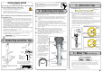
Hole positioning: Position the tap such that it dispenses into
the sink bowl with ample clearance for a cup or tea pot. Alternatively,
the tap could be mounted away from the sink using a Zip Font,
available as an accessory.
Apply a light smearing of silicon sealant on
the underside of the upper spacer to ensure a
watertight fi t.
For HydroTap & Mixer taps : cut a 35mm hole in the bench or sink top.
BENCH TOP
Ø35mm
1 - HydroTap and Elite Tap
4 - Mixer Tap (5-in-1 BCS only)
ALL THREAD
ROD
STAINLESS
STEEL
WASHER
SPIDER
CLAMP
NUT
BLACK
PLASTIC
SPACER
NOTE: feed each of the three tubes and
electrical cable evenly in between the legs of
the SPIDER CLAMP when installing.
Fit the
STAINLESS STEEL
WASHER,
SPIDER CLAMP,
AND 6mm NUT.
6mm
NUT
SPIDER
CLAMP
Stainless
washer
Black plastic
spacer
35mm dia hole
Sink
•
F
it the O-ring into the recess on the underside of the Mixer tap. (Note: If mounting on an
uneven surface, a light smear of silicone on the seal ring will ensure a water tight seal)
• Affix the three hoses to the tap, matching their colours to the tube extension colours.
• Pass all hoses through the 35mm hole and position the tap so that it discharges into the
sink.
• Fit the lower rubber seal to the threaded extension.
• Secure the tap in position with the metal washer and N
ut.
2 - HydroTap Arc/Cube
The HydroTap Arc/Cube has a spout that may be fixed in one of 6 angular positions
(depending on the position of the rotary control) and fixed in one of two height positions.
The spout is fixed and does not swivel.
NOTE: The tube kit must be fitted after the HydroTap has been mounted on the benchtop
or sink. Refer to the tube kit assembly instructions, supplied with the tap kit.
1.
Remove the 2 x spout locating screws and lower the spout to expose the plastic
spring clip
NOTE: The plastic spring clip has two internal dimples that may be positioned in
the 6 upper or 6 lower, pre drilled holes in the spout (see diags. below )
2.
To reposition the spout, gently spread the plastic spring clip to release the dimples
from the spout holes. When released, slide the clip on the spout so that it ends up
between the two rows of holes.
3.
Rotate the plastic clip on the spout to orient the dimples, so they are in line with the
newly selected holes.
NOTE: When determining which of the 6 holes are required for the new spout
height and orientation, check the new plastic clip position will clear the
undercut and that the wiring loom will not be pinched, when assembled.
4.
Slide the plastic clip up/down to engage with the selected holes, making sure the
two dimples engage simultaneously with the two selected holes.
NOTE: The clip will not fit correctly if one dimple engages before the other. Both
dimples must engage at the same time.
5.
With the clip fitted to the newly
selected holes, carefully raise
the spout (ensure the wiring
loom is a neat fit in the undercut
and is located between the open
ends of the clip) until the clip
locating holes are in line with
the spout locating screws.
6.
Replace the 2 x locating screws.
7.
If mounting on an uneven
surface, apply a light smearing
of silicon sealant on the O ring
to ensure a watertight fit.
8.
Pass the assembly through the
35mm hole and position the tap
so it discharges into the sink.
9.
Fit the lower rubber seal to the
threaded extension.
10.
Secure the tap in position with
the metal washer and nut.
11.
Fit the tube kit, as supplied
Spout locating
screws (2)
Plastic spring
clip
Upper locating
positions
Lower locating
positions
Clip locating
holes (2)
Undercut
for loom
Plastic spring clip
Dimples
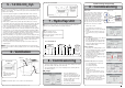
3 - All-In-One Tap
For All-In-One taps cut a 50mm hole in the bench or sink top.
50mm
Bench top
Note
Note: make sure the tap location will allow the nozzle to drain into the sink.
BCS Residential models
Vented braided hose positions
BLUE to
Mixer IN
WHITE
Mains IN
RED from
Mixer OUT
Mains braided hose positions
HOT IN
from HWS
Underside view
BLUE
Mains IN
RED
• Fit the seal ring to the base of the tap and
If mounting on an uneven surface, a light
smear of silicone on the seal ring will ensure a water tight seal.
• Mount the tap on top of the cut out hole after passing the usb cable and tubes through the
50mm hole
• Thread the cable and silicon tubes through the circular clamp block (Check the tube colour
matches with the coloured dots on the clamp block). (See below)
• Clamp the assembly in position using the threaded nut and clamp block
• Working from inside the cupboard, attach the braided hoses to the tube extensions (Use the
o-ring grease, supplied, to ensure the seals on the end of the hoses are lubricated). Check the
correct position for Hot and Cold connections by matching the colours on the braided hoses
with the coloured markings on the copper extension tubes. (See below)
• Test for leaks after all the connections have been secured.
CLAMP
BLOCK
Braided
hoses
Extension
tubes
Typical Vented assembly