
Guide

801624 - Chiller Quick Start Guide - July 2015 - V2.00
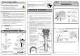
STEP 3 - Install the undersink unit
Note: Remove any plugs from the top of the undersink unit connections and Install the
mains water braided hoses to the undersink unit before locating the unit in place..
HydroTap Unit
Min.
35mm
280mm
Note:
-
Mains hose length is
750mm and the Plug
and Cord length is
1800mm
Position the under sink
unit close to the outlet
tap, within reach of the
hose and cord lengths
supplied.
Max.
500mm
Max.
1490mm
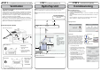
STEP 4 - Commission the HydroTap
The following instructions are critical if the vent kit, as
supplied, is not fitted:
If the kick board vent kit cannot be used then it is important to fit a standard
HydroTap vent kit, which ensures heat dissipation through natural convection
via installed vents. For high use applications, where the cupboard space
temperature is near 35°C, or higher, an auxillary ventilation kit must be fitted.
(contact your local service centre for availability).
Note: The vent kit has to be installed in a way that allows air to be drawn in
from the bottom of the cupboard and expelled through the top of the cupboard.
Therefore placement of the outlet vent should be towards the top of the door
(Option 1) or on the side of the cupboard (Option 2).
POWER
CORD
USB
CHILLED
OUTLET
MAINS
IN
BLUE BRAIDED
Note: All silicon tubes must be cut to size. They must have a constant fall back to
the unit.
Note: The tube lengths are matched to the pumps performance and therefore
CANNOT be lengthened
Commissioning
Ventilation
STEP 2 - Cut cupboard holes and fit the air vent ducts
1.
Turn the stop cock ON
2.
Press [Start] button to start filter flush.
3.
Allow at least 10 litres of water to flush
through the filter.
4.
Once the filter flush is finished, Turn
the stop cock OFF then press [Stop] to
end filter flush mode.
5.
Press [Next] and the View screen will
show the Flow calibration mode.
6.
Press the [Start] button and the
tank will first empty then fill. Upon
completion the actual pulse will be
displayed. Check this reading is within
the limits
For other configurations,
see the main installation
instructions
OPEN Position
CLOSED Position
ON
OFF
Stop cock
operation
Have a 10L bucket or similar container (not
supplied) at the ready to hold a quantity of
water that will be ejected while the Filter
Flush Mode is in operation. Open the filter
access door on the front of the HydroTap
and the filter cartridge will be exposed.
Located to the rear RHS of the cartridge is a
flush line, approx 600mm long and the flush
line stop cock. Place the valve end of the
flush line into the 10L bucket or container.
Filter Flush:
Before Commissioning:
• Turn ON the water and check for any leaks.
• Turn the power ON at the GPO
• Familiarise yourself with the operation of the Tap, in preparation for use (See
User Guide)
• Follow the Installation instructions below (and review Section C of the User
Guide).
• After commissioning, the system may be customised by selecting further
options in Section G - Settings, within the User Guide.
Language selection:
Side outlet vent (Option 2)
Door outlet
vent
(Option 1)
Front inlet vent
Cool Air IN
Warm Air OUT
Airflow through the cupboard
Cutout details
Air inlet vent
B
D
Door outlet vent
1.
Drill four pilot holes
12mm dia.
2.
Finish the cutout using
a jig saw and keyhole or
Wall Board saw
Cutout details
D
B