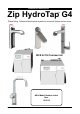
Installation Instructions Zip HydroTap G4 ® Filtered Boiling, Chilled and Sparkling drinking water for commercial kitchens and tea rooms. BCS & CS Commercial Affix Model Number Label Here 801910 801910 - Zip Sparkling HydroTap - Installation Instructions - July 2015 - V2.
Tap options The G4 applaince series offers a range of interchangeable taps to suit the customer’s needs These three taps are directly compatible with the G4 under bench unit. The Mixer tap range is an additional series of taps that may be used in conjunction with any one of the three taps shown above, to create 4-IN-1 models The All-In-One Tap is a stand alone tap that may be used as an alternative to any of the above combinations. The A-I-O is compatible with the G4 underbench unit.
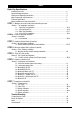
Index HydroTap Specifications Installation check list .................................................................................................................... 4 Important Safety Instructions ....................................................................................................... 5 Warnings and Regulatory Information.......................................................................................... 6 Major components and Accessories .........................................
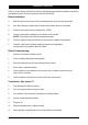
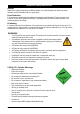
Installation checklist Thank you for purchasing a Zip HydroTap. Please read and follow these instructions carefully to ensure safe and trouble free service. If service is required, please call 1800 638 633 Before Installation: A. Read the instructions and check if there is adequate space to mount all of the components. B. Note: Not all fittings are supplied with the appliance kit. Isolation valves are not supplied. C. Check the mains water pressure is between 250 - 700kPa D.
Important Safety Instructions What is the Zip HydroTap ? The Zip HydroTaps are electronically controlled, filtered, Boiling, Chilled and Sparkling water, drinking systems for kitchens and tea rooms. The HydroTap units are under bench drinking water appliances with a dispensing tap mounted on a sink or bench, which may be used for residential or commercial applications.
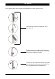
Important Safety Instructions Altitude Water boils at varying temperatures at different altitudes. Your HydroTap adjusts for this during startup calibration and will recalibrate itself on a regular basis. Frost Protection If this appliance is located where the ambient air temperature could fall below 5ºC when the heater is not in use, do not turn off the appliance electrically. This safeguard does not offer the same protection to the connecting pipework and fittings.
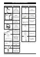
Major components and accessories Parts supplied Description Accessories 1 off 4 HydroTap Taps with hoses (Cl;assic tap shown) Description Softener and head assembly 1 off HydroTap Underbench Unit with air and water filters Font Kit for Arc & Cube Models 1 off Mains water connection hose Font Kit for Classic & Elite Models Duct kit 1 x Air Duct 1 x Mounting plate Replacement Filter Vent Kit 1 x Kickboard louvre 1 x Door vent louvre 1 x Front vent grill Disabled lever Kit 1 off HydroTap Booster H
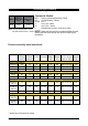
Technical Specifications Cups of Boiling Water per Hour Glasses of Chilled Water per Hour Commercial Models: = Boiling, Chilled and Sparkling, Filtered, = Chilled Sparkling, Filtered = 5 in 1 = All in One - Mains BCS 160 175 = All in One - Vented = Disabled lever controls, (Order as an option) Note: the Cup measurement =167ml the Glass measurement = 200ml NOTE: chilled water will continue to be dispensed after the rated capacity has been used, although this may be at slightly higher temperature.
Before Installation Before installing ensure that the following have been provided at the Installation site: • Review all the technical specifications. • Ensure the underbench can support the product weight when full of water, (allow an extra 4-5kg when full. ) • Sufficient space in the cupboard to install all of the undersink units in accordance with these Installation Instructions. Refer to technical specification for dimensions. Make allowance for a booster heater and / or water softener if required.
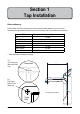
Section 1 Tap Installation Hole positioning: Position the tap such that it dispenses into the sink bowl with ample clearance for a cup or tea pot. Alternatively, the tap could be mounted away from the sink using a Zip Font, available as an accessory.
HydroTap Classic & Elite EliteTap Min 300mm HydroTap Classic ALL THREAD ROD BLACK PLASTIC SPACER 335mm STAINLESS STEEL SPACER SPIDER CLAMP 470mm NUT Tap assembly exploded view and kitchen layout side view. 1.1 1.2 BENCH TOP Ø35mm Apply a light smearing of silicon sealant on the underside of the spacer to ensure a watertight fit. Cut a 35mm hole in the bench / sink top. 801910 - Zip Sparkling HydroTap - Installation Instructions - July 2015 - V2.
Installation Instructions 1.4 1.3 BLACK PLASTIC SPACER STAINLESS STEEL WASHER Fit the STAINLESS STEEL WASHER, SPIDER CLAMP, AND 6mm NUT. SPIDER CLAMP 6mm NUT 35mm hole Pass all the hoses, tubes and USB lead through the 35mm hole. Note: feed each of the three tubes and electrical cable evenly in between the legs of the SPIDER CLAMP when installing. 1.5 Typical HydroTap Installation (see section 5) Blue & White hoses to chilled sparkling water outlet Note: All silicon tubes must be cut to size.
HydroTap Arc/Cube The HydroTap Arc/Cube has a spout that may be fixed in one of 6 angular positions (depending on the position of the rotary control) and fixed in one of two height positions. The spout is fixed and does not swivel. NOTE: The tube kit must be fitted after the HydroTap has been mounted on the benchtop or sink. Refer to the tube kit assembly instructions, supplied with the tap kit. To reduce the risk of scalding, Position A should not be selected with any of the Boiling water units. (See fig.
Installation Instructions 1.7 Height adjustment (Fixed position options) 50mm 1.8 Angular adjustment (Fixed position options) Left Hand Control Right Hand Control NOTE: Position A is not recommended with Boiling water units A 1.9 B C C B A Mounting (See table on Page 11 ) BENCH TOP O-RING LOWER RUBBER WASHER Ø35mm WASHER Cut a 35mm hole in the bench / sink top. Page 14 of 44 NUT 801910 - Zip Sparkling HydroTap - Installation Instructions - July 2015 - v2.
Min 300mm Mixer Tap Installation BRAIDED HOSE x 3 Tap assembly exploded view and kitchen layout side view. 1.11 O-RING 1.10 SINK TOP LOWER RUBBER WASHER 35mm WASHER Cut a 35mm hole in the bench / sink top. NUT Note: make sure the tap location will allow the nozzle to drain into the sink. Red band Mixer Out Note: The mixer tap requires a Zip Restrictaflow valve, as supplied, to be fitted in the cold water supply line, from the isolation valve tee piece, to the mixer tap. (See Fig. 1.
Installation Instructions 1.12 Installing the Mixer Tap (Classic, Arc and Cube) • Fit the O-ring into the recess on the underside of the Mixer tap. (Note: If mounting on an uneven surface, a light smear of silicone on the O-ring will ensure a water tight seal) • Pass the tap tubes and threaded extension through the 35mm hole and position the tap so that it discharges into the sink. • Fit the lower rubber seal to the threaded extension. • Secure the tap in position with the metal washer and Nut.
Installation Instructions Typical HydroTap 5-in-1 Installation (see section 6) 1.13 MIXER MIXER OUT IN CLEAR POWER USB CO2 CHILLED SPARKLING MAINS IN OUTLET OUTLET CORD IN RED BRAIDED WHITE BLUE GAS IN Note: All silicon tubes must be cut to size. They must have a constant fall back to the unit.
All-In-One Tap Installation 335mm Min 300mm 1.14 470mm 1.15 SINK TOP 50mm Cut a 50mm hole in the bench / sink top. Note: make sure the tap location will allow the nozzle to drain into the sink.
Installation Instructions 1.16 Clamp Block markings and silicon tube positions, viewed from underneath BLUE mark WHITE mark BLUE mark RED mark SILICON TUBES R B B R C C USB CABLE AIO Vented assy AIO Mains assy CLAMP BLOCK 1.
Installation Instructions Typical Vented assembly 1.18 • Screw the braided hoses into the extension tubes. Ensure the o-rings are lubricated prior to assembly and that the braided hoses, with coloured markings, are correctly matched with the colours on the extension tubes and on the clamp block (as indicated). Vented braided hose positions WHITE Mains IN CLAMP BLOCK Extension tubes • Make sure all tubes and hoses are firmly secured.
Installation Instructions 1.20 Typical All-In-One Vented assembly with Booster heater Note: - Mains hose length is 750mm - Plug and Cord length is 1800mm Note: All silicon tubes must be cut to size. They must have a constant fall back to the unit.
Section 2 Ventilation When installing air flow ducts, the following tools will be required: • Jigsaw and 12mm drill • Keyhole or Wall Board saw. Recommended Installation showing the correct air flow MIN. 50mm Air Gap Cool Air IN via cabinet floor, front vent grille 2.1 **MIN. 100mm Warm Air OUT via kickboard louvre Ventilation for All Models Proper air circulation must be provided for all Boiling and Boiling Chilled Sparkling models.
Ventilation 2.2 Chilled Sparkling ventilation Typical Cut out arrangement for Chilled Sparkling models with kickboard venting via a left hand appliance duct C B A 2.3 Boiling Chilled Sparkling ventilation Typical Cut out arrangement for Boiling Chilled Sparkling models with kickboard venting via a right hand appliance duct C B A 801910 - Zip Sparkling HydroTap - Installation Instructions - July 2015 - V2.
Ventilation CUT OUT DETAILS A - KICKBOARD CUT-OUT 1.Drill 4 pilot holes Ø12 in corners 2.Finish cut-out using Jigsaw and Keyhole or Wall Board saw = 60.00 = 285.00 12 .0 0 ATTENTION: Insure that: Cut outs 'A' and 'B' are on opposite side of cabinet. Cut out 'C' is straight behind'A' 314.00 B - CABINET FLOOR CUT-OUT max 43 5 .00 12 12 .0 0 Min 450mm 326.00 1.Drill two pilot holes Ø12 2.Finish cut-out using Jigsaw 45.
Section 3 Booster Heater 3.1 Product Description The boost unit is a compact electronically controlled auxiliary water heater. It is intended to provide pre heating of water before it enters the Zip HydroTap G4 boiling tank. The Booster is supplied as standard equipment with all 240 cup models. However, it may be later installed, as an accessory for the 160 cup models, to increase their delivery to 240 cups. Note 1: water connection :Blue marking - water in :Red marking - water out.
Booster Installation 3.2 Installation Procedure Site requirements • Appliance must only be installed in a frost-free area. Never expose appliance to frost. • The Appliance is designed for wall mounted Installation and must to be installed with water connectors facing upwards. • The appliance complies with protection class IP 25. • The 400mm braided hoses supplied with the unit cannot be lengthened. • The 90° elbow hose ends, should be fitted to the inlet and outlet connections on top of the Booster.
Booster System Note 1: This appliance is intended for use with the Zip HydroTap under sink unit. Note 2: Water connections must be pointing vertically upwards. Note 3: The booster unit should be installed as close as possible to the Zip HydroTap Unit as the 400mm connection hoses cannot be lengthened. 3.4 Braided hose connections The cold water inlet (blue) and hot water outlet (red) are marked on the rating plate.
Section 4 Filter / Softener Installation An external filter / Softener may be fitted to reduce the incidence of scale build up in the hot tank or may be at the customer’s request. 4.1 Mounting the filter head • Choose a suitable location, (cupboard back or side wall) within the reach of the braided hoses. • Mount the filter head bracket in an upright position, using the screws supplied in the kit • Ensure there is enough headroom for the filter cartridge to be easily fitted and removed.
Section 5 2.640 KG - CO2 Cylinder STORAGE WARNING: This cylinder mus be installed in an open plan area or in an enclosed room, with a volume no less than 50m3. If more than 1 gas cylinder containing CO2 is present within the same location, the recommended ventilated area should be in proportion to the number of gas cylinders stored in that location. A ventilated area is a non-enclosed area which could include the kitchen, living room etc. See gas bottle and MSDS sheet for a complete list of warnings.
CO2 Regulator This gauge shows the adjustable limit (2.7- 3.0 bar) required for the HydroTap to function correctly This gauge shows the pressure in the bottle and indicates when the bottle is empty. Initial bottle pressure will be 35-40 bar. Green zone Relief valve ON - OFF knob NOTE: be careful not to lose the small sealing olive in the end of the braided hose. This olive is necessary to ensure a gas tight seal between the braided hose and the regulator. Pressure regulating knob 5.
Section 6 Underbench Unit Installation Note: Before you install a unit, determine whether a water softener or an external filter is required. 6.1 External Bypass Valve The diverter bypass valve allows the user to choose to have the boiling feed water bypass the internal filter and only be filtered by the external filtration. This diverter valve is located at the rear panel of the Zip HydroTap underbench unit on the filter door side, see the image below.
Installation Instructions MIXER MIXER OUT IN CLEAR POWER USB CO2 CHILLED SPARKLING MAINS CORD IN OUTLET OUTLET IN RED Note: All silicon tubes must be cut to size. They must have a constant fall back to the unit. BRAIDED WHITE BLUE Models BCS 160/175 GAS IN 6.3 BOILING OUT BYPASS VENT BYPASS IN OUT Note: - Mains hose length is 750mm - Plug and Cord length is 1800mm Max. 1000mm Min.
Installation Instructions MIXER MIXER OUT IN CLEAR POWER USB CO2 CHILLED SPARKLING MAINS CORD IN IN OUTLET OUTLET Booster Note: All silicon tubes must be cut to size. They must have a constant fall back to the unit. RED BRAIDED WHITE BLUE Model BCS 240/175 GAS IN 6.
Installation Instructions MIXER MIXER OUT IN CLEAR POWER USB CO2 CHILLED SPARKLING MAINS IN OUTLET OUTLET IN CORD Note: All silicon tubes must be cut to size. They must have a constant fall back to the unit. RED BRAIDED WHITE BLUE Model All-In-One Mains Pressure - BCSHA 160/175 GAS IN 6.
Installation Instructions Model All-In-One Vented - BCSHA-AV 240/175 MIXER MIXER OUT IN CLEAR POWER USB CO2 CHILLED SPARKLING MAINS IN CORD IN OUTLET OUTLET RED BRAIDED WHITE BLUE Note: All silicon tubes must be cut to size. They must have a constant fall back to the unit. Booster HydroTap AIO Connections GAS IN 6.
Installation Instructions Model HydroTap 5-In-1 Vented - BCSHA 160/175 MIXER MIXER OUT IN CLEAR POWER USB CO2 CHILLED SPARKLING MAINS IN OUTLET OUTLET CORD IN RED BRAIDED WHITE BLUE Note: All silicon tubes must be cut to size. They must have a constant fall back to the unit. HydroTap Mixer Connections GAS IN 6.
Installation Instructions Model HydroTap 5-In-1 Vented with a Booster - BCSHA 240/175 MIXER MIXER OUT IN CLEAR POWER USB CO2 CHILLED SPARKLING MAINS IN OUTLET OUTLET CORD IN RED BRAIDED WHITE BLUE Note: All silicon tubes must be cut to size. They must have a constant fall back to the unit. Booster HydroTap Mixer Connections GAS IN 6.
Installation Instructions CO2 IN CHILLED OUTLET BRAIDED WHITE BLUE Chilled Sparkling Model - CS 175 GAS IN 6.9 SPARKLING OUTLET USB POWER CORD Note: All silicon tubes must be cut to size. They must have a constant fall back to the unit.
Section 7 Commissioning The HydroTap is now ready to be commissioned. • Turn ON the water and gas and check for any leaks. • Turn the power ON at the GPO and at the side of the undersink unit • If fitted, ensure the Booster is turned OFF. (The Booster is commissioned, later, at section 7.4) • Familiarise yourself with the operation of the Tap, in preparation for use (See User Guide) • Follow the Installation instructions below (and review Section C of the User Guide).
Commissioning OPEN Position ON Stop cock operation CLOSED Position OFF 7.3 - Boiling Calibration (Boiling models) • Press the calibration button and the system will commence the Boiling calibration procedure. This will take approx 5-6 minutes. 7.4 - Booster (240/175 models) • Upon completion, a Booster reminder screen will appear and allow you to return home by pressing the [Home] button.
Commissioning To enabled when a Booster unit is installed. 1. 2. 3. 4. 5. 6. 7. Press the [MENU] button for main menu. Press the [Install] button. Press the [Booster] button. In the next screen, press YES to enable the Booster. Turn the Booster ON Water must be run through the Booster for a min of 30 seconds, before the heater will activate. Dispense boiling water for 30 secs and check the Booster outlet hose is warm when the boiling water tank is replenishing.
Trouble Shooting System Fault Message Power board fault Interface fault Level board fault Condenser screen blocked Water leak, Isolate mains Compressor over-run Water supply failed Hot sensor Open Hot sensor Closed Cold sensor Open Cold sensor Closed Flood sensor Open Condenser sensor Closed Condenser sensor Open Heater fuse / driver fault Heater driver fault Compressor driver fault Hot sensor degraded Condenser overtemp.
Notes 801910 - Zip Sparkling HydroTap - Installation Instructions - July 2015 - V2.
Contact Details Head Office Zip Heaters (Aust) Pty. Ltd. ABN: 46 000 578 727 67 Allingham Street Condell Park NSW 2200 Postal: Locked Bag 80 Bankstown 1885 Australia Website: www.zipwater.com Facsimile: (02) 9796 3858 Telephone: (02) 9796 3100 Free Call: 1 800 638 633 As Zip policy is one of continuous product improvement, changes to specifications may be made without prior notice. Images in this booklet have been modified and may not be true representations of the finished goods.