
Guide

801913 - BCS. CS. Quick Start Guide - July 2015 - v2.00
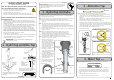
Note: Remove all caps from the top of the undersink unit and Install the mains water
braided hoses to the undersink unit before locating the unit in place..
7 - HydroTap Unit
8 - Commissioning
RED
CLEAR
BLUE
BRAIDED
WHITE
GAS IN
POWER
CORD
USB
CHILLED
OUTLET
MAINS IN
MIXER OUT MIXER IN
BOILING
OUT
BYPASS IN VENT BYPASS
OUT
SPARKLING
OUTLET
CO2
GAS
Note:
Insulate the
Blue and
the White
tubes after
Trimming to
length
OPEN Position
CLOSED Position
ON
OFF
Stop cock
operation
Have a 10L bucket or similar container (not
supplied) at the ready to hold a quantity of
water that will be ejected while the Filter
Flush Mode is in operation. Open the filter
access door on the front of the HydroTap
and the filter cartridge will be exposed.
Located to the rear RHS of the cartridge is a
flush line, approx 600mm long and the flush
line stop cock. Place the valve end of the
flush line into the 10L bucket or container.
1.
Turn the stop cock ON
2.
Press [Start] button to start filter flush.
3.
Allow at least 10 litres of water to flush
through the filter.
4.
Once the filter flush is finished, Turn the stop
cock OFF then press [Stop] to end filter flush
mode.
Flow Calibration:
1.
Press [Next] and the View screen will
show the Flow calibration mode.
2.
Press the [Start] button and the tank will
first empty then fill. Upon completion the
actual pulse will be displayed. Check this
reading is within the limits
Boiling Calibration:
1.
Press [Next] for the Boiling Calibration
screen.
2.
Press the calibration button and the system
will commence the Boiling calibration
procedure. This will take aprox 5-6 minutes.
3.
Upon completion, a Booster reminder screen
will appear and allow you to return home by
pressing the [Home] button.
4.
Check the Date and Time settings (See
section G of the user guide)
To enable the Booster: (when installed)
• Press the [MENU] button for main menu.
• Press the [Install] button.
• Press the [Booster] button.
• In the next screen, press YES to enable the
Booster.
• Turn the Booster ON
• Water must be run through the Booster for
a min of 30 seconds, before the heater will
activate.
• Dispense boiling water for 30 seconds and
check the Booster outlet hose is warm when
the boiling water tank is replenishing.
Note
Note: Failing to make the correct selection for the
“Booster”, will affect product performance.
Filter Flush:
Commissioning the HydroTap
1.
Press the [START] button to
commence the purging process.
2.
Purge for 5 seconds and ensure all
water has stopped flowing through
the tap. (You will hear the CO
2
gas
escaping from the tap).
3.
Press the [Stop] button.
4.
Press [Next] for the filter flush
screen
CO
2
Purge: (Sparkling models)
Turn on the water and gas to check for any leaks before turning on the power.
The system will promp you to select a language before continuing with the filter flush
procedure
8 - Commissioning
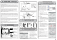
6 - Ventilation
= =
max 43
314.00
12.00
12.00
285.00
12.00
5
326.00
A
A - KICKBOARD CUT-OUT
1.Drill 4 pilot holes Ø12 in corners
2.Finish cut-out using Jigsaw
and Keyhole or Wall Board saw
B - CABINET FLOOR
CUT-OUT
1.Drill two pilot holes Ø12
2.Finish cut-out using Jigsaw
C - CABINET FLOOR
CUT-OUT
1.Drill 4 pilot holes
Ø12 in corners
2.Finish cut-out using Jigsaw
and Keyhole or Wall Board saw
ATTENTION:
Insure that: Cut outs 'A' and 'B' are on opposite side of cabinet.
Cut out 'C' is straight behind'A'
60.00
B
C
12.00
45.00
284
Note: For alternative options, refer to section 2 of the main instructions
For positioning of cutout C use the template
marked on the cardboard carton
Min. 450mm
Cut out arrangement for
Chilled Sparkling models
with venting via a left hand
appliance duct.
Allow sufficient side clear-
ance for cut out
Maintain 100mm clear-
ance between &
cut outs
A
B
C
Typical BCS cut out for
R/H vented models
Side outlet vent (Option 2)
Door outlet
louvre
(Option 1)
Front inlet vent
Cool Air IN
Warm Air OUT
Typical airflow for sparkling models when no kickboard venting is possible
C
A B
Min
100mm
Mixer
Mixer
connections
connections
Booster
Booster
5 - 2.640 KG - CO
2
Cyl.
This cylinder must be installed in an open plan area or in an enclosed room, with a
volume no less than 50m
3
. See details on the gas bottle and in the MSDS sheet for
a complete list of warnings.
1- After removing all packing material, mark out the cradle location, and fit it on a
suitable wall, within 1 metre of the unit. Make sure the gas bottle, regulator and
cradle assembly can comfortably fit, with sufficient clearances, before securing the
cradle inside the cupboard. Due to regulatory requirements the gas bottle must be
stored securely and in an upright position. Secure the bottle with the hook-and-loop
straps provided.
2- After unpacking, fit the regulator to the gas bottle. Ensure the plastic seal is
fitted securely inside the large chrome nut, before attaching to the gas bottle.
If the plastic seal is not an easy fit over the spigot, soak it in hot water, before
re-applying. Do not force the seal to fit. Turn the regulator OFF by rotating the
regulator knob, all the way out, in an anti-clockwise direction.
NOTE: Two plastic seals are supplied with a new regulator. Only one is required,
the other is supplied as a spare part.
3- Connect the braided gas hose to the top of the underbench unit via the John
Guest fitting marked ‘Gas IN’ Then connect the threaded end to the regulator (Do
not lose the small sealing olive). When commissioning, turn the gas ON by rotating
the valve on top of the cylinder, anti-clockwise. Then adjust the outlet pressure, by
rotating the regulator knob in a clockwise direction, to between 2.7- 3.0 bar (green
zone)
NOTE:
The arrow should sit in the green zone of the regulator gauge; it should not
fall in the red or yellow sections.
4 -When commissioning, use soapy water to perform a leak test. Apply the soapy
water to the two gas connections using a sponge or brush. If any bubbles appear
and grow, there is a gas leak at the connection. Clean away the soapy residue
and tighten or refit the leaking connection. Make sure the gas is turned off when
tightening or refitting the leaking connection.
Fit the gas bottle into the cradle and secure with the Hook-and-loop strap. Ensure
the bottle is in an upright position.
NOTE:
Care must be taken when working with high pressure carbon dioxide,
and in no case should the normal operating pressure of between 2.7- 3.0 bar be
exceeded.