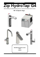
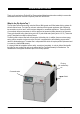
Installation Instructions Zip HydroTap G4 ® Filtered boiling and chilled drinking water for commercial kitchens and tea rooms. BC Compact range Affix Model Number Label Here 802411 802411 - HT Compact Commercial BC, BCHA -AV, AIO, Installation Instructions - Aug 2015 - V2.
Notes Page 2 of 40 802411 - HT Compact Commercial BC, BCHA-AV, AIO, Installation Instructions - Aug 2015 - V2.
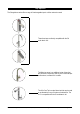
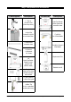
Tap options The G4 applaince series offers a range of interchangeable taps to suit the customer’s needs These three taps are directly compatible with the G4 under bench unit. The Mixer tap range is an additional series of taps that may be used in conjunction with any one of the three taps shown above, to create 4-IN-1 models The All-In-One Tap is a stand alone tap that may be used as an alternative to any of the above combinations. The A-I-O is compatible with the G4 underbench unit.
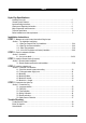
Index HydroTap Specifications Installation check list .................................................................................................................... 5 General Product Features ............................................................................................................ 6 Important Safety Instructions ....................................................................................................... 7 Warnings and Regulatory Information...............................
Installation checklist Before Installation: A. Read the instructions and check if there is adequate space to mount all of the components. B. Note: Not all fittings are supplied with the appliance kit. Isolation valves are not supplied. C. Check the mains water pressure is between 172 - 700kPa and 200 - 700 kPa when a booster is installed D. Check the water quality to determine if extra filtration will be required. NOTE: This product must be fitted to a potable water supply E.
General Product Features Thank you for purchasing a Zip HydroTap. Please read and follow these instructions carefully to ensure safe and trouble free service. If service is required, please call 1800 460 222 What is the Zip HydroTap ? The Zip HydroTaps are electronically controlled, filtered, Boiling water and Chilled water drinking systems for kitchens and tea rooms.
Important Safety Instructions This manual contains important safety, Installation instructions for the Zip HydroTap G4. Safety This appliance is not intended for use by persons (including children) with reduced physical, sensory or mental capabilities, or lack of experience and knowledge, unless they have been given supervision or instruction concerning use of the appliance by a person responsible for their safety. Children should be supervised to ensure that they do not play with the appliance.
Important Safety Instructions Positioning It is important to ensure the undersink unit is positioned in an accessible area close to the floor level. The unit must have it’s base mounted in a horizontal position with all inlets and outlets facing up. The Tap must be located above the undersink unit and positioned so that it dispenses into the sink bowl with ample clearance for a cup or tea pot. See section 1 for details. WARNINGS 1. 2. 3. 4. 5. 6. 7. 8. 9.
Major components and accessories Parts supplied Description Accessories 1 x Tap option with hoses (Classic tap shown) 1 x HydroTap Undersink Unit with air and water filters 1 x Mains water connection hose Vent Kit 1 x Inlet vent 1 x Outletvent 9 x Screws Description HydroTap Booster Water System with connection hoses Font Kit for Arc & Cube Models Font Kit for Classic & Elite Models Replacement Filter 1 off HydroTap Booster Heater & hoses.
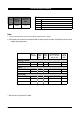
Technical Specifications Model Cups of Boiling Water per Hour BC Models Glasses of Chilled Water per Hour 100 75 BC Boiling and Chilled BCHA 4 in 1 A All in One - Mains AV All in One - Vented D Disabled lever controls (optional accessory) Note: 1. The Cup measurement =167ml and the Glass measurement = 200ml 2. Chilled water will continue to be dispensed after the rated capacity has been used, although this may be at slightly higher temperature.
Before Installation Before installing ensure that the following have been provided at the Installation site: • Review all the technical specifications. • Ensure the underbench can support the product weight when full of water, (allow an extra 4-5kg when full. ) • Sufficient space in the cupboard to install all of the undersink units in accordance with these Installation Instructions. Refer to technical specification for dimensions. Make allowance for a booster heater and / or water softener if required.
Section 1 Tap Installation Hole positioning: Position the tap such that it dispenses into the sink bowl with ample clearance for a cup or tea pot. Alternatively, the tap could be mounted away from the sink using a Zip Font, available as an accessory.
HydroTap & Elite Installation EliteTap HydroTap Classic Min 300mm ALL THREAD ROD STAINLESS STEEL SPACER BLACK PLASTIC SPACER 335mm SPIDER CLAMP NUT 470mm Tap assembly exploded view and kitchen layout side view. 1.1 1.2 BENCH TOP Ø35mm Apply a light smearing of silicon sealant on the underside of the spacer to ensure a watertight fit. Cut a 35mm hole in the bench / sink top. 802411 - HT Compact Commercial BC, BCHA -AV, AIO, Installation Instructions - Aug 2015 - V2.
Installation Instructions 1.4 1.3 BLACK PLASTIC SPACER Fit the STAINLESS STEEL WASHER, SPIDER CLAMP, AND 6mm NUT. STAINLESS STEEL WASHER SPIDER CLAMP 6mm NUT 35mm hole Pass all the hoses, tubes and USB lead through the 35mm hole. Note: feed each of the three tubes and electrical cable evenly in between the legs of the SPIDER CLAMP when installing. 1.5 Typical HydroTap Installation (see section 5) Red hose to boiling water outlet Note: All silicon tubes must be cut to size.
HydroTap - Arc/Cube The HydroTap Arc/Cube has a spout that may be fixed in one of 6 angular positions (depending on the position of the rotary control) and fixed in one of two height positions. The spout is fixed and does not swivel. NOTE: The tube kit must be fitted after the HydroTap has been mounted on the benchtop or sink. Refer to the tube kit assembly instructions, supplied with the tap kit. To reduce the risk of scalding, Position A should not be selected with any of the Boiling water units.
Installation Instructions 1.7 Height adjustment (Fixed position options) 50mm 1.8 Angular adjustment (Fixed position options) Left Hand Control Right Hand Control NOTE: Position A is not recommended with Boiling water units A 1.9 B C C B A Mounting (See table on Page 10 ) BENCH TOP O-RING LOWER RUBBER WASHER Ø35mm WASHER Cut a 35mm hole in the bench / sink top. Page 16 of 40 NUT 802411 - HT Compact Commercial BC, BCHA-AV, AIO, Installation Instructions - Aug 2015 - V2.
Min 300mm Mixer Tap Installation BRAIDED HOSE x 3 Tap assembly exploded view and kitchen layout side view. 1.11 O-RING 1.10 SINK TOP LOWER RUBBER WASHER 35mm WASHER Cut a 35mm hole in the bench / sink top. NUT Note: make sure the tap location will allow the nozzle to drain into the sink. Red band Mixer Out Note: The mixer tap requires a Zip Restrictaflow valve, as supplied, to be fitted in the cold water supply line, from the isolation valve tee piece, to the mixer tap.
Installation Instructions 1.12 Installing the Mixer Tap (Classic, Arc and Cube) • Fit the O-ring into the recess on the underside of the Mixer tap. (Note: If mounting on an uneven surface, a light smear of silicone on the O-ring will ensure a water tight seal) • Pass the tap tubes and threaded extension through the 35mm hole and position the tap so that it discharges into the sink. • Fit the lower rubber seal to the threaded extension. • Secure the tap in position with the metal washer and Nut.
Installation Instructions 1.13 Typical 4-In-1 Installation (see section 4) Booster Note: All silicon tubes must be cut to size. They must have a constant fall back to the unit.
All-In-One Tap Installation 335mm Min 300mm 1.14 470mm 1.15 SINK TOP 50mm Cut a 50mm hole in the bench / sink top. Note: make sure the tap location will allow the nozzle to drain into the sink.
Installation Instructions 1.16 Clamp Block markings and silicon tube positions, viewed from underneath BLUE mark WHITE mark BLUE mark RED mark SILICON TUBES R B B R C C USB CABLE AIO Vented assy AIO Mains assy CLAMP BLOCK 1.
Installation Instructions Typical Vented assembly 1.18 • Screw the braided hoses into the extension tubes. Ensure the o-rings are lubricated prior to assembly and that the braided hoses, with coloured markings, are correctly matched with the colours on the extension tubes and on the clamp block (as indicated). CLAMP BLOCK Extension tubes • Make sure all tubes and hoses are firmly secured.
Installation Instructions 1.20 Typical All-In-One Vented assembly with Booster (See section 4) Booster Restrictaflow valve & Tee (Supplied) COLD isolation valve (Not supplied) Restrictaflow valve Note: The All-In-One vented taps require a Zip Restrictaflow valve and Tee piece, as supplied, to be fitted in the cold water supply line, from the isolation valve (Not supplied), to the mixer tap. (See diagrams) Note: All plastic tubes must be cut to size. They must have a constant fall back to the unit.
Section 2 Ventilation 2.1 Ventilation for All Models Proper air circulation must be provided for all models. The system will operate correctly only if the recommended air gaps are achieved during installation. The minimum requirement is for a 50mm air gap either side and 300mm above of the undersink unit. It is important that the 4mm door buffers (For all installations ) are fitted to the inside edge of the cupboard door to allow suficient air circulation inside the cupboard. (See the diagram below).
Ventilation When installing air flow ducts, the following tools will be required: • Jigsaw and a 12mm Drill • Keyhole or Wall Board saw. 2.2 The following instructions are critical if there is insufficient cupboard air circulation. If the air flow, using the silicon door buffers, is insufficient, it will be necessary to fit a standard HydroTap vent kit, which ensures heat dissipation through natural convection via installed vents.
Ventilation Typical Cut out procedure for B D Mark out and cut the air inlet and door outlet holes as shown 2. Ensure the air inlet vent and air outlet vent are positioned at opposite ends of the same cupboard space. 3. Fit the inlet vent, as shown and secure with 5 screws 4. Fit the outlet vent, as shown in the hottest part (top) of the cupboard and secure with 4 screws 1.
Section 3 Booster Heater 3.1 Product Description The boost unit is a compact electronically controlled auxillary water heater. It is intended to provide pre heating of water before it enters the Zip HydroTap G4 boiling tank. The Booster is supplied as standard equipment with all 140 cup models. However, it may be later installed, as an accessory for the 100 cup models, to increase their delivery to 140 cups. Note1: water connection :Blue marking - water in :Red marking - water out.
Booster Installation 3.2 Installation Procedure Site requirements • Appliance must only be installed in a frost-free area. Never expose appliance to frost. • The Appliance is designed for wall mounted Installation and must to be installed with water connectors facing upwards. • The appliance complies with protection class IP 25. • The 300mm braided hoses supplied with the unit cannot be lengthened. • The 90° elbow hose ends, should be fitted to the inlet and outlet connections on top of the Booster.
Booster System NOTE1: This appliance is intended for use with the Zip HydroTap under sink unit. NOTE2: Water connections must be pointing vertically upwards. NOTE3: The booster unit should be installed as close as possible to the Zip HydroTap Unit as the 300mm connection hoses cannot be lengthened. 3.4 Braided hose connections The cold water inlet (blue) and hot water outlet (red) are marked on the rating plate.
Section 4 Undersink Unit Installation Note: Before you install an undersink unit, determine whether a water softener or an external filter is required. 4.1 External Bypass Valve The diverter bypass valve allows the user to choose to have the boiling water filtered either by the internal or by an optional external filter. This diverter valve is located at the rear panel of the Zip HydroTap undersink unit on the filter door side, see the image below.
Installation Instructions MAINS IN MIXER OUT MIXER IN BOILING OUT BYPASS IN VENT BYPASS OUT BLUE RED Note: All silicon tubes must be cut to size. They must have a constant fall back to the unit. CLEAR Model: Boiling Chilled BC100/75 BRAIDED 4.3 CHILLED OUT USB POWER CORD Note: - Mains hose length is 750mm - Plug and Cord length is 1800mm Max. 1000mm Min. 50mm Clearance 280mm Position the under sink unit close to the outlet tap, within reach of the hose and cord lengths supplied Max.
Installation Instructions MAINS IN MIXER OUT MIXER IN BOILING OUT BYPASS IN BLUE RED Note: All silicon tubes must be cut to size. They must have a constant fall back to the unit. CLEAR Model: All-In-One Mains Pressure BRAIDED 4.
Installation Instructions 4.5 Model: All-In-One Vented Booster RED BRAIDED MIXER IN BOILING OUT BYPASS IN BLUE BRAIDED MIXER OUT BRAIDED BRAIDED MAINS IN CLEAR BRAIDED HT Mixer connections VENT BYPASS OUT CHILLED OUT Note: All silicon tubes must be cut to size. They must have a constant fall back to the unit.
Installation Instructions 4.6 Model: 4-In-One Vented Booster Note: All silicon tubes must be cut to size. They must have a constant fall back to the unit.
Section 5 Commissioning • • • • • • Turn ON the water and gas and check for any leaks. Turn the power ON at the GPO and at the side of the undersink unit If fitted, ensure the Booster is turned OFF. (The Booster is commissioned, later, at section 5.5) Familiarise yourself with the operation of the Tap, in preparation for use (See User Guide) Follow the Installation instructions below (and review Section C of the User Guide).
Commissioning 5.4 - Boiling Calibration • Press the calibration button and the system will commence the Boiling calibration procedure. This will take aprox 5-6 minutes. 5.5 - Booster • Upon completion, a Booster reminder screen will appear and allow you to return home by pressing the [Home] button. • Check the Date and Time settings (See Note below) NOTE: Failing to make the correct selection for the “Booster”, will affect product performance.
Safety Sensor Calibration (Lever taps) 5.6 - Sensor Light intensity varies from site to site, therefore it is recommended that a re-calibration be performed at the time of the installation. All direct natural sun light must be shaded from the HydroTap, during the calibration. This can be achieved by closing any nearby curtains, blinds, or by shielding the HydroTap with a dark cloth. Pull both levers forward Safety sensor 1. 2. 3. 4. 5. 6. 7.
Trouble Shooting System Fault Message Possible Cause Power board fault Interface fault Level board fault Condenser screen blocked Water leak, Isolate mains Compressor over-run Water supply failed Hot sensor Open Hot sensor Closed Cold sensor Open Cold sensor Closed Flood sensor Open Condenser sensor Closed Condenser sensor Open Heater fuse / driver fault Heater driver fault Compressor driver fault Hot sensor degraded Condenser overtemp.
End of Life Disposal In order to help preserve our environment we ask that you dispose of this product correctly. Please contact your local city council for collection centre details. 802411 - HT Compact Commercial BC, BCHA -AV, AIO, Installation Instructions - Aug 2015 - V2.
Contact Details Head Office Zip Heaters (Aust) Pty. Ltd. ABN: 46 000 578 727 67 Allingham Street Condell Park NSW 2200 Postal: Locked Bag 80 Bankstown 1885 Australia Website: www.zipheaters.com Facsimile: (02) 9796 3858 Telephone: (02) 9796 3100 Free Call: 1 800 638 633 As Zip policy is one of continuous product improvement, changes to specifications may be made without prior notice. Images in this booklet have been modified and may not be true representations of the finished goods.