
Installation and Operation Guide

20
Quick Start Installation Guide
807120 v1.00 01.21 G5 C CS Quick Start Guide
For HydroTap, mixer tap and any optional accessories, use
instructions supplied with individual kit components.
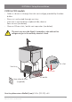
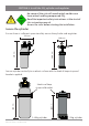
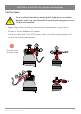
SECTION 10: Connect the Command Centre
Generic installation instructions
Connections key
HydroTap
CO
Braided hose
Command
Centre
USB
Tap
Mains power cable
Do not connect to the mains
socket until commissioning
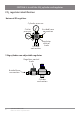
USB CO
2
IN
CHILLED
OUTLET
SPARKLING
OUTLET
MAINS
IN
MIXER
OUT
MIXER
IN
BOILING
OUT
BYPASS
IN
VENT BYPASS
OUT
MAINS
IN
MIXER
OUT
MIXER
IN
BOILING
OUT
BYPASS
IN
VENT BYPASS
OUT
CHILLED
OUTLET
SPARKLING
OUTLET
CO
2
IN
USB
BCS comm
BCS res
BC comm
CHILLED
OUTLET
MAINS
IN
MIXER
OUT
MIXER
IN
BOILING
OUT
BYPASS
IN
VENT BYPASS
OUT
USB
MAINS
IN
MIXER
OUT
MIXER
IN
BOILING
OUT
BYPASS
IN
VENT BYPASS
OUT
CHILLED
OUTLET
USB
BC res
MAINS
IN
MIXER
OUT
MIXER
IN
BOILING
OUT
BYPASS
IN
VENT BYPASS
OUT
AMBIENT
OUTLET
USB
BA res comm
MAINS
IN
MIXER
OUT
MIXER
IN
BOILING
OUT
BYPASS
IN
VENT BYPASS
OUT
B res comm
USB
MAINS
IN
C 175 comm
USB
CHILLED
OUTLET
CS 175 comm
CO
2
IN
CHILLED
OUTLET
SPARKLING
OUTLET
MAINS
IN
C res
CHILLED
OUTLET
MAINS
IN
USB
CS75 res
CO
2
IN
CHILLED
OUTLET
SPARKLING
OUTLET
MAINS
IN
USB
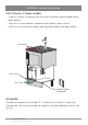
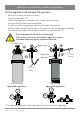
check USB
position
check which way round
still / sparkling
Installation diagrams are for illustrative purposes only. Hoses are
not shown to scale and cannot be lengthened.
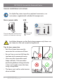
!
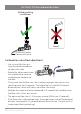
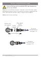
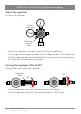
Tips for hose connection
• Push the silicone hose over the
connector for a minimum of 15mm.
• Ensure there a constant fall from the
tap down to the command centre.
• Hoses must be trimmed to avoid
loops and kinks. Take care when
positioning before cutting and make
a clean cut straight across the hose,
using a sharp blade.
• The hoses must not be under tension
when installed.