
Specification Sheet

Water Pressure
Water Connection
Integral Water Values
Water Supply Requirements
Total Dissolved Solids (TDS)
Integral Water Filter
Power Rating
Power Supply Requirements
Dimensions (WxDxH)
Minimum Air Gap
Dry Weight
Product Approvals
Warranty
CO
2 Cylinder
CO
2 Operating Pressure
CO
2 Cylinder
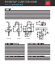
COMMAND CENTER SPECS
Min 30psi – Max 75psi with a minimum ow rate of 1 gpm
½” BSP - isolation valve is required within 3’ of the installation
HydroTaps are tted with a Dual Check Valve and a 50psi Pressure Limiting Valve
Potable drinking water supply
TDS Min 50ppm – Max 120ppm
0.2 micron, 1 size - Replace every 1,500 gallons or 12 months
110-120V, 60 Hz, 0.235kW
110-120V, 60Hz 15 amp power supply with a NEMA 5-15 outlet
11” x 16” x 13.1”
Clearances are required - 2” Left side , 2” Right side , 8”Above
85lbs
WQA - NSF/ANSI 372, 42 & 53, cUL, CEC
2 years (1 year Limited Warranty plus additional 1 year Warranty is available on product registration)
2 x 1.5lb Beverage Grade Carbon Dioxide Cylinder
Approximately 950 8oz cups
Min 39psi - Max 43psi
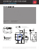
Installation and connection of your HydroTap must be carried out by a qualied person, observing all local, state, & federal regulations. You will require suitable 110 -120V 60Hz 15 amp power supply with a NEMA 5-15
electrical outlet within 3’ of the product. The HydroTap is an air-cooled system, so discrete cabinetry cut-outs are required for ventilation. Installation on most counter tops is straightforward, however some stone
counter tops may require a specialized cutting service. If using a drip tray (font) accessory, suitable drainage to a trapped waste is required within 3’ of the installation. If you live in an area with hard water (more than
120ppm), we recommend installation of a scale ltration kit. Sufcient space and clearance to install the HydroTap as detailed in the product installation guidelines is required. Installation by Zip Professional Service
can be arranged with a phone call to 1-833-233-2358 or through www.us.zipwater.com
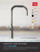
HYDROTAP
®
CUBE FOR HOME
A
A
.
1
8
SECTION A-A
3mm ( )
buffer pad
air space
(406
mm
)
16"
Position the Tap to dispense into the sink
bowl with ample clearance for a cup or a carafe.
Alternatively, the Tap may be mounted away from
the sink using a Zip Font, available as an accessory.
1 "
hole
Sink shown only
3
8
Sample
Tap
IEC Flex & Plug
110-120V, 60Hz
power outlet
CO gas
cylinder
2
(82
mm
)
3.2"
Mains cold water
isolation valve
(not supplied)
Clearance
Envelope
(333
mm
)
13.1"
min
7.9"
min
(200
mm
)
11.5"
(292
mm
)
DETAIL B: CABINET FLOOR CUT-OUT
VENTILATION DETAIL
See Detail B
11
16
1
" max
15
16
12
"
(326
mm
)
3
16
"
(5
mm
)
1
8
8 "
(207
mm
)
(35
mm
)
(43
mm
)
2.0"
min
(50
mm
)
2.0"
min
(50
mm
)
11"
min
(280
mm
)
19ZIP016_CubeCS_240v_v1