
User Manual


06 806143 - CW ChillTap UCCT 10.18 v1.03
Installation instructions
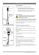
Clearance
Envelope
Ventilation
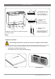
When installing air flow ducts, the following tools will be required:
•
Jigsaw and 12 mm drill.
•
Keyhole or Wall Board saw.
Ventilation Requirements
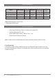
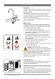
IMPORTANT! Allow clearance of 50 mm around and 200 mm above the chiller unit.
Proper air circulation must be provided for the system to operate correctly. Both the top and the front of the chiller
must remain accessible for servicing.
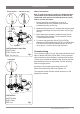
Fit the 3 mm silicon door buffers to the inside edge of the cupboard door (Fig.3).
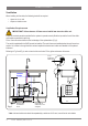
The vent kit supplied with the ChillTap must be installed. The vent kit ensures heat dissipation through forced con-
vection. Air is drawn in through the front vent and expelled via the duct and outlet vent installed in the cupboard
kickboard.
Referring to Fig.3 and Fig.4, mark out and cut the vent holes. Fit the grilles and secure with screws.
3 mm
Buffer Pad
Clear Gap
477
*100mm
Warm Air OUT
via kickboard
louvre
50
mm
Cool Air IN via
cabinet floor, front
vent grille
* Note: Inlet and outlet vents should be separated by a minimum of 100 mm, to avoid hot air recirculation.
550mm
50
mm
Fig.3