
User manual

Control Unit and RTU Installation Procedure
Document Number: ECP 05-9531
Version: 2.0
Date: 03/09/2014
© UK Power Networks 2014 All rights reserved 9 of 29
9 Positioning and Configuration
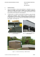
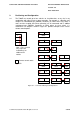
9.1 The T200E can control up to four switches or circuit-breakers at any site, in any
combination with either linear or rotary operation. For example, a substation may
comprise of switchboard one (SWBD1) containing an RE2c where ring switch 1
and 2 and the coupled SE6 (linear operation) are all automated and in addition
switchboard two (SWBD2) containing an RN2c where just ring switch 1 is
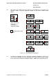
automated. The diagrams shown in Figure 9-1 provide examples of the various
remote control options.
SE6RE2c
RN2c
2
RN2c
2
RN2c
4
RN2c
RN2c
2
RN2c
2
SE6RE2c
SE6RE2c
SE6RE2c
T200
4
1
2
3
1
1
1
1
1
1
3
3
4
4
4
3
2
2 3
4
RN2c SE6RE2c
1 2 3 4
Note – FPI 2, 3 and 4
may require the
installation of an
additional FPI
module
FPI
x Remote control switch
Figure 9-1 – Schneider Switchgear Configurations