
User manual

Control Unit and RTU Installation Procedure
Document Number: ECP 05-9531
Version: 2.0
Date: 03/09/2014
© UK Power Networks 2014 All rights reserved 3 of 29
Contents
1 Introduction ............................................................................................................. 5
2 Scope ....................................................................................................................... 5
3 References ............................................................................................................... 5
4 Abbreviations and Definitions ................................................................................ 5
5 Description............................................................................................................... 6
6 Equipment ................................................................................................................ 6
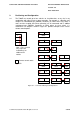
7 Communications ..................................................................................................... 7
8 Location ................................................................................................................... 8
9 Positioning and Configuration ............................................................................... 9
10 Mains Supply ......................................................................................................... 11
10.1 General ................................................................................................................... 11
10.2 LV Transformer-mounted Fuse Cabinet ................................................................... 11
10.3 LV Pillar ................................................................................................................... 12
10.4 LV Main (Switching Stations) ................................................................................... 13
10.5 Consumer Units (Indoor Substations) ...................................................................... 14
10.6 HV Metering Unit (HV Customers and Switching Stations) ...................................... 14
11 Earthing .................................................................................................................. 14
12 Labelling ................................................................................................................ 14
13 Final Checks .......................................................................................................... 14
Appendix A – Control Unit Details ................................................................................... 15
A.1 Schneider T200E ..................................................................................................... 15
A.2 Schneider T200E Series 3 ....................................................................................... 16
A.3 Lucy Gemini ............................................................................................................ 17
Appendix B – Plinth Drawings ......................................................................................... 18
B.1 Schneider T200E Plinth ........................................................................................... 18
B.2 Lucy Gemini Plinth................................................................................................... 19
Appendix C – Stand Drawings ......................................................................................... 20
C.1 Lucy Gemini Stand used for Ground Mounting ........................................................ 20
C.2 Lucy Gemini Stand used for Wall Mounting (e.g. GRP) ........................................... 21
Appendix D – GRP Mounting Arrangements ................................................................... 22
D.1 GRP RTU Fixing Drawing ........................................................................................ 22
D.2 Lucy Gemini GRP Mounting Arrangements ............................................................. 23
Appendix E – Material Lists .............................................................................................. 24
E.1 Auxiliary Supply Components .................................................................................. 24
E.2 Automation Components ......................................................................................... 25