
User manual
Control Unit and RTU Installation Procedure
Document Number: ECP 05-9531
Version: 2.0
Date: 03/09/2014
© UK Power Networks 2014 All rights reserved 14 of 29
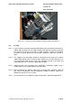
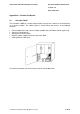
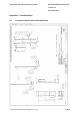
10.5 Consumer Units (Indoor Substations)
10.5.1 Where an indoor substation has existing domestic supply available then these
should be adapted to provide an un-switched metal clad spur adjacent to the
control unit. Wherever possible the supply for the control should be wired as a
separate circuit from the local consumer unit and protected by a 3A fuse in the spur
with appropriate circuit protection at the consumer unit.
10.5.2 Label the un-switched spur 'CAUTION - Automation Supply' using a suitable label
so as to avoid inadvertent disconnection.
10.5.3 A list of materials to assemble this supply arrangement is detailed in Appendix E.
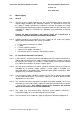
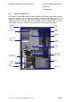
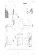
10.6 HV Metering Unit (HV Customers and Switching Stations)
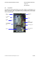
10.6.1 An alternative option for use at HV customer sites or switching stations is to use a
HV metering unit. An 110V supply can be taken from the metering unit auxiliary
supply terminals to power the control unit.
Note: The T200E control unit requires the installation of an 110V input transformer
(available from Schneider) to facilitate this. The original 230V input transformer
should be left in the control unit for future use.
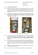
11 Earthing
11.1 If the control unit is mounted onto a wall or free standing frame then it shall be
suitably bonded to the substation earthing using minimum of 35mm
2
stranded
aluminium or 16mm
2
stranded copper PVC covered earth cable as specified in
ECS 06-0023.
11.2 If the control unit is mounted onto the switchgear the installed control unit bonding
braid shall be securely attached to the switchgear earth.
11.3 The mains supply cable shall be earthed at the control unit end only (and not at the
supply end). The earth shall be insulated at the other end.
12 Labelling
12.1 If the control unit is controlling more than one switchboard at a location then the
door of control unit should be clearly labelled as shown in Appendix F.
12.2 Each switch in the control unit shall be clearly labelled to indicate which circuit it is
controlling as shown in Appendix F.
13 Final Checks
13.1 Check that:
The cabinet is secure.
The mains supply is complete.
The earthing is complete.
The correct labels are fitted.