
User manual

Control Unit and RTU Installation Procedure
Document Number: ECP 05-9531
Version: 2.0
Date: 03/09/2014
© UK Power Networks 2014 All rights reserved 13 of 29
10.4 LV Main (Switching Stations)
10.4.1 Where no LV supply is available from a transformer-mounted fuse cabinet, LV pillar
or existing domestic wiring within a substation building then a new service with a
minimum capacity of 16A shall be installed. Typically this will require a new service
from a passing LV main but in some circumstances considerably more work maybe
involved.
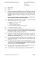
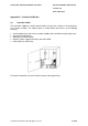
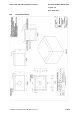
10.4.2 If the substation is outdoors the new service should be terminated using a street
lighting pillar. The street lighting pillar should contain an un-switched spur for the
control unit and a socket outlet as shown in Figure 10-2. A standard 'Danger' notice
shall be attached to the pillar.
Figure 10-2 – Mains Supply using a Street Lighting Pillar
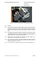
10.4.3 If the substation is indoors, including a GRP enclosure, the new service should be
mounted onto a meter-board securely fitted to the structure. The opportunity should
be taken to fit an un-switched spur for the control unit and a socket outlet as a
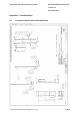
minimum. A list of materials to assemble such a supply arrangement is shown in
Appendix E.
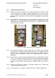
10.4.4 Install a 2.5mm
2
steel-wire armoured cable between the street lighting pillar and the
control unit. To avoid a parallel earth path the armouring shall only be earthed at
the control unit end with a suitable gland. The street lighting pillar end should be
secured in a plastic gland. Any unused cores should be made safe and left as
spare.
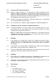
10.4.5 Label the un-switched spur 'CAUTION - Automation Supply' using a suitable label
to avoid inadvertent disconnection.
10.4.6 A list of materials to assemble this supply arrangement is detailed in Appendix E.