
User manual

Control Unit and RTU Installation Procedure
Document Number: ECP 05-9531
Version: 2.0
Date: 03/09/2014
© UK Power Networks 2014 All rights reserved 12 of 29
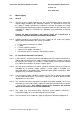
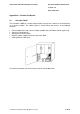
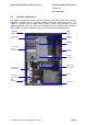
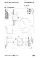
Figure 10-1 – Transformer-mounted Cabinet Auxiliary Supply Terminal Block
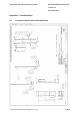
10.3 LV Pillar
10.3.1 Install a 2.5mm
2
steel-wire armoured cable between the transformer-mounted fuse-
cabinet and the control unit. To avoid a parallel earth path the armouring shall only
be earthed at the control unit end with a suitable gland, the LV pillar end should be
secured in a plastic gland. Any unused cores should be made safe and left as
spare.
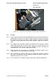
10.3.2 The supply to the automation should be connected to the existing LV auxiliary
supply; either directly from an existing spare auxiliary fuse (fused at 5A or less) or
via a metal-clad fused-spur (fused at 3A), mounted securely in the pillar and
supplied directly from an auxiliary supply within the pillar.
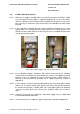
10.3.3 Label the fused spur or auxiliary fuses 'CAUTION - Automation Supply' using a
suitable label so as to avoid inadvertent disconnection.
10.3.4 The connection of an auxiliary supply from an existing pillar should be subject to
both careful consideration and any proposed method of working subject to a
detailed site specific risk assessment.
10.3.5 A list of materials to assemble this supply arrangement is detailed in Appendix E.