
User manual
Control Unit and RTU Installation Procedure
Document Number: ECP 05-9531
Version: 2.0
Date: 03/09/2014
© UK Power Networks 2014 All rights reserved 11 of 29
10 Mains Supply
10.1 General
10.1.1 The type of mains supply will depend on the actual installation and the type of low
voltage supply available at the substation. However, it is important to ensure that
the supply is reliable and robustly installed as it will not only power the remote
control equipment and keep the battery charged but it will also give indication of the
availability of supply to a substation, thus providing useful information to aid fault
restoration.
Caution: All work to facilitate a low voltage supply for a control unit is
covered by UK Power Networks Distribution Safety Rules.
10.1.2 Suitable procedures for installing the mains supply for the various low voltage
options below and detailed in the sections that follow.
LV transformer-mounted fuse cabinet.
LV pillar.
LV main (switching stations).
Consumer unit (indoor substations).
HV metering unit (HV customers and switching stations).
10.2 LV Transformer-mounted Fuse Cabinet
10.2.1 Install a 2.5mm
2
steel-wire armoured cable between the transformer-mounted fuse-
cabinet and the control unit. To avoid a parallel earth path the armouring shall only
be earthed at the control unit end with a suitable gland, the transformer-mounted
fuse-cabinet end should be secured in a plastic gland.
10.2.2 The transformer-mounted fuse-cabinet should be inspected and assessed for the
availability of an auxiliary supply; typically a fused supply is available at a
connection block in the bottom of the cabinet but other options especially in older
equipment may need to be considered.
10.2.3 A fused auxiliary supply should be confirmed as live and un-switched (for example
via the cabinet door switch). The auxiliary supply fuse should be proved and the
appropriate fuse way noted.
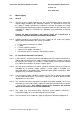
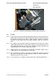
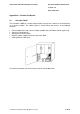
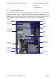
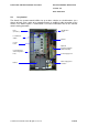
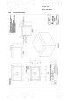
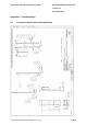
10.2.4 The standard transformer-mounted fuse-cabinet (Schneider) provides for an easy
connection of a 6A fused auxiliary supply for automation (H2-H5 'External Lighting'
– refer to Figure 10-1). This auxiliary supply source should be the preferred
option for the control unit on all new installations.
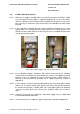
10.2.5 The supply fuse and terminal block should be clearly labelled 'CAUTION –
Automation Supply' so as to avoid inadvertent disconnection.
10.2.6 A list of materials to assemble this supply arrangement is detailed in Appendix E.