Document Number: ECP 05-9531 Date: 03/09/2014 ENGINEERING CONSTRUCTION PROCEDURE ECP 05-9531 CONTROL UNIT AND RTU INSTALLATION PROCEDURE Network(s): EPN, SPN Summary: This document details the installation procedure for the control units and remote terminal units (RTU) used with ground-mounted switchgear. It includes the physical installation of the control unit together with installation of the mains supply, earthing and communications.
Control Unit and RTU Installation Procedure Document Number: ECP 05-9531 Version: 2.0 Date: 03/09/2014 Revision Record Version 2.0 Review Date 27/07/2015 Date 03/09/2014 Author James Ford Update: Location section added (Section 8) to specify RTU location for safe egress by operator Version 1.2 Review Date 27/07/2015 Date 17/10/2012 Author Stephen Tucker Minor Update: Document renumbered from ECP 11-0531. Earth conductor sizes amended (section 10). Reviewed for G81 website Version 1.
Control Unit and RTU Installation Procedure Document Number: ECP 05-9531 Version: 2.0 Date: 03/09/2014 Contents 1 Introduction ............................................................................................................. 5 2 Scope ....................................................................................................................... 5 3 References ...............................................................................................................
Control Unit and RTU Installation Procedure Document Number: ECP 05-9531 Version: 2.0 Date: 03/09/2014 Appendix F – Labels ......................................................................................................... 27 F.1 Control Unit Door Label for Multiple Switchboards ................................................... 27 F.2 T200E Circuit Label ................................................................................................. 28 F.3 Gemini Circuit Label ..............
Control Unit and RTU Installation Procedure Document Number: ECP 05-9531 Version: 2.0 Date: 03/09/2014 1 Introduction 1.1 This document details the installation procedure for the control units and remote terminal units (RTU) used with ground-mounted switchgear. It includes the physical installation of the control unit together with installation of the mains supply, earthing and communications. 1.
Control Unit and RTU Installation Procedure Document Number: ECP 05-9531 Version: 2.0 Date: 03/09/2014 5 Description 5.1 The Schneider T200E and Lucy Gemini 2 are control units/RTUs that are used to provide local and remote control of secondary switchgear. A description of these units is given in Appendix A. 5.2 New switchgear ordered with remote control will generally be supplied and delivered to site with the remote control already fitted.
Control Unit and RTU Installation Procedure Document Number: ECP 05-9531 Version: 2.0 Date: 03/09/2014 7 Communications 7.1 Prior to the installation of remote control switchgear it is advisable to carry out a Paknet communications survey using a Paknet test set (CS1051 or CS106-6) to determine if a suitable signal strength is available. If this cannot be achieved UK Power Networks Operational Telecoms (or your UKPN nominated contact) should be consulted so that an alternative can be established. 7.
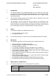
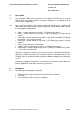
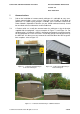
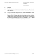
Control Unit and RTU Installation Procedure Document Number: ECP 05-9531 Version: 2.0 Date: 03/09/2014 8 Location 8.1 The RTU should be situated such that an operator has safe egress from the substation after operation which would usually mean a location near the main door of the substation. 8.2 Generally the Schneider T200E control unit is supplied mounted directly onto the switchgear which is satisfactory for most installations. 8.
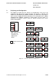
Control Unit and RTU Installation Procedure Document Number: ECP 05-9531 Version: 2.0 Date: 03/09/2014 9 Positioning and Configuration 9.1 The T200E can control up to four switches or circuit-breakers at any site, in any combination with either linear or rotary operation.
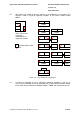
Control Unit and RTU Installation Procedure Document Number: ECP 05-9531 Version: 2.0 Date: 03/09/2014 9.2 The Gemini can control up to three switches or circuit-breakers at a location. The diagrams shown in Figure 9-2 provide examples of the various remote control options.
Control Unit and RTU Installation Procedure Document Number: ECP 05-9531 Version: 2.0 Date: 03/09/2014 10 Mains Supply 10.1 General 10.1.1 The type of mains supply will depend on the actual installation and the type of low voltage supply available at the substation.
Control Unit and RTU Installation Procedure Document Number: ECP 05-9531 Version: 2.0 Date: 03/09/2014 Figure 10-1 – Transformer-mounted Cabinet Auxiliary Supply Terminal Block 10.3 LV Pillar 10.3.1 Install a 2.5mm2 steel-wire armoured cable between the transformer-mounted fusecabinet and the control unit. To avoid a parallel earth path the armouring shall only be earthed at the control unit end with a suitable gland, the LV pillar end should be secured in a plastic gland.
Control Unit and RTU Installation Procedure Document Number: ECP 05-9531 Version: 2.0 Date: 03/09/2014 10.4 LV Main (Switching Stations) 10.4.1 Where no LV supply is available from a transformer-mounted fuse cabinet, LV pillar or existing domestic wiring within a substation building then a new service with a minimum capacity of 16A shall be installed. Typically this will require a new service from a passing LV main but in some circumstances considerably more work maybe involved. 10.4.
Control Unit and RTU Installation Procedure Document Number: ECP 05-9531 Version: 2.0 Date: 03/09/2014 10.5 Consumer Units (Indoor Substations) 10.5.1 Where an indoor substation has existing domestic supply available then these should be adapted to provide an un-switched metal clad spur adjacent to the control unit.
Control Unit and RTU Installation Procedure Document Number: ECP 05-9531 Version: 2.0 Date: 03/09/2014 Appendix A – Control Unit Details A.1 Schneider T200E The Schneider T200E has remote control facilities for up to four switches or circuit-breakers (or a mixture of both). The cabinet layout is shown below and consists of the following elements: Control module (left card), Comms module (middle card) and Power module (right card). Space for Paknet pad etc. Switchgear interface module.
Control Unit and RTU Installation Procedure Document Number: ECP 05-9531 Version: 2.0 Date: 03/09/2014 A.2 Schneider T200E Series 3 The T200E can be used to control Schneider switchgear (with rotary and/or linear actuators) and other switchgear via the standard secondary switchgear telecontrol interface. The T200E can also be used to control retrofit actuators on legacy oil switchgear using an additional interface card. Each switch to be controlled needs an umbilical cable connection to the T200E.
Control Unit and RTU Installation Procedure Document Number: ECP 05-9531 Version: 2.0 Date: 03/09/2014 A.3 Lucy Gemini The Gemini has remote control facilities for up to three switches or circuit-breakers (or a mixture of both). Each switch to be controlled needs an umbilical cable connection to the Gemini. The cabinet layout is shown below. For further information refer to the relevant commissioning procedure.
Control Unit and RTU Installation Procedure Document Number: ECP 05-9531 Version: 2.0 Date: 03/09/2014 Appendix B – Plinth Drawings B.
Control Unit and RTU Installation Procedure Document Number: ECP 05-9531 Version: 2.0 Date: 03/09/2014 B.
Control Unit and RTU Installation Procedure Document Number: ECP 05-9531 Version: 2.0 Date: 03/09/2014 Appendix C – Stand Drawings C.
Control Unit and RTU Installation Procedure Document Number: ECP 05-9531 Version: 2.0 Date: 03/09/2014 C.2 Lucy Gemini Stand used for Wall Mounting (e.g.
Control Unit and RTU Installation Procedure Document Number: ECP 05-9531 Version: 2.0 Date: 03/09/2014 Appendix D – GRP Mounting Arrangements D.
Control Unit and RTU Installation Procedure Document Number: ECP 05-9531 Version: 2.0 Date: 03/09/2014 D.
Control Unit and RTU Installation Procedure Document Number: ECP 05-9531 Version: 2.0 Date: 03/09/2014 Appendix E – Material Lists E.1 Auxiliary Supply Components List of useful items to assist in the installation of control unit auxiliary supplies.
Control Unit and RTU Installation Procedure Document Number: ECP 05-9531 Version: 2.0 Date: 03/09/2014 E.2 Automation Components The tables below contain a summary of the key components that maybe required as replacements/spares or to facilitate the addition of remote control to new or existing switches or circuit breakers.
Control Unit and RTU Installation Procedure Document Number: ECP 05-9531 Version: 2.0 Date: 03/09/2014 Table E-3 – Schneider Extensible Switches (SE6) and Circuit-Breaker (CE6/CE2) Components 6 Item Materials Code (Supplier Reference) Linear actuator SE6 CE2/CE6 48776Q 48776Q 1.
Control Unit and RTU Installation Procedure Document Number: ECP 05-9531 Version: 2.0 Date: 03/09/2014 Appendix F – Labels F.1 Control Unit Door Label for Multiple Switchboards If a control unit controls more than one switchboard a warning label (approx size 300mm x 150mm) shall be fixed onto the front of the as shown below. .
Control Unit and RTU Installation Procedure Document Number: ECP 05-9531 Version: 2.0 Date: 03/09/2014 F.2 T200E Circuit Label The label shown below is provided on the inside of the door on a T200E and is supplied on all EPN and SPN units from September 2008. Spare labels for use on older stock are available from Schneider Electric. Engraved circuit labels of size 55mm x 25mm shall be added for each switch/circuit-breaker in use as shown below.
Control Unit and RTU Installation Procedure Document Number: ECP 05-9531 Version: 2.0 Date: 03/09/2014 F.3 Gemini Circuit Label Engraved circuit labels of size 55mm x 25mm shall be added for each switch in use as shown below.