
User Guide


<%27
7UGT
U/CPWCN
80 2YHUYLHZ
•
Add
•
Subtract
•
Logical AND
•
Logical OR
•
Logical Exclusive OR
•
Compare
•
Left or Right Shifts or Rotates (Arithmetic and Logical)
•
Increment
•
Decrement
•
Set Bit
•
Reset Bit
•
Test bit
,QVWUXFWLRQ5HJLVWHUDQG&38&RQWURO
As each instruction is fetched from memory, it is placed in the
INSTRUCTION register and decoded. The control sections performs this
function and then generates and supplies the control signals necessary to
read or write data from or to the registers, control the ALU, and provide
required external control signals.
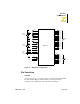
3,1'(6&5,37,21
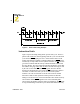
2YHUYLHZ
The Z80 CPU I/O pins are illustrated in Figure 3 and the function of each
is described in the following paragraphs.