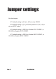
Jumper settings Set the Jumper JP1 default setting is [1-2], to (2-3) to clear CMOS. JP4 default setting is [1-2] to Panel speaker out, to (2-3) to mix out AC97 codec . JP6 default setting is OPEN, to Enable AC97 CODEC, to CLOSE to Disable AC97 CODEC. JP7 default setting is OPEN, to Enable MC97 CODEC, to CLOSE to Disable MC97 CODEC.
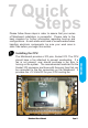
7 Quick Steps Please follow these steps in order to assure that your series of Mainboard installation is successful. Please refer to the back chapters for further information regarding boot-up and configurations. An anti-static wrist band is recommended when handling electronic components, be sure your work area is static free before you begin this section. The Mainboard provides a 370 pins, Socket 370. The CPU should have a fan attached to prevent overheating.
CAUTION! Be sure that sufficient air circulation must be available across the processor’s heatsink. Without sufficient circulation, the processor could overheat and damage both the processor and the mainboard. You may install an auxiliary fan if necessary.
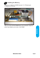
Installing the Memory Memory is installed in DIMM Sockets 1-3 (F Mainboard in diagram) as follows : 7 Quick Steps After you have set the DIMM firmly into its socket, snap the white chip holders up to lock in the DIMM.
Attaching ATX Power Supply. ATX Power Supply Connector (20-pin ATXPWR) The single 20-pin connector (B in mainboard diagram) incorporates standard +/-5V and +/-12V, with a standby 5V. With a power supply that supports remote power on/off, the mainboard can turn off the system power through the software control, such as the shutdown in Windows 95 Start Menu. The BIOS system will turn the system power off when it receives the proper APM command from the OS.
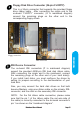
Floppy Disk Drive Connector (34-pin FLOPPY). This is a 34-pin connector that supports the provided floppy drive ribbon cable. After connecting the single end to the on-board “FLOPPY” connector, (O in mainboard diagram) connect the remaining plugs on the other end to the corresponding floppy drives. IDE connection IDE Device Connector. The on-board IDE connectors (P in mainboard diagram) support the provided 40/80-pin IDE hard disk ribbon cable.
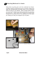
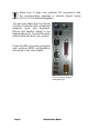
Mounting Mainboard to chassis Snap black mounting pins onto the mainboard as shown. Carefully install the mainboard into the computer chassis and align the corresponding mounting holes on the mainboard with the holes on you chassis. While chassis design varies you may need to refer to the chassis manual for the mainboard mounting area. Insert white pins through the chassis and through the mounting holes on the mainboard into the black pin making sure they are snapped fully into place.
Installing Add-in Boards 7 Quick Steps First read your expansion card documentation for hardware and software settings that may be required to set up your specific card. Set any necessary jumpers on your expansion card and remove the cover plate on your computer case at the slot you intend to use. Keep the plate for possible future use. Carefully align the card's connector and press firmly. Secure the card on the slot with the screw you removed from the cover plate.
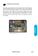
Make sure to align rear external I/O connector's with the corresponding openings in chassis shown below (A,C & G in mainboard diagram) You can now attach the Front Panel Function Connector (M in mainboard diagram) wires and Keyboard, Mouse and Monitor cables to the appropriate ports. Connect the main power cable and boot your system. Press the DEL key when prompted and continue BIOS configurations discussed in the next chapter.