
User's Manual


Glossary
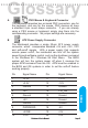
N Flash BIOS
The Mainboard flash BIOS provides users with more flexibility
in upgrading their mainboards. The flash BIOS can be easily
reprogrammed via software.
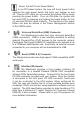
O Floppy Drive Header
The Mainboard provides a 34-pin connector that supports
the included floppy drive ribbon cable. After connecting the
single end to the on-board “FLOPPY” connector, connect
the remaining plugs on the other end of the cable to the
corresponding floppy drives.
NOTE: Pin 5 is removed to prevent inserting the connector
in the wrong orientation.
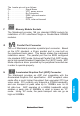
P IDE Device Header
The Mainboard provides (2) independent bus-mastering PCI
IDE interfaces capable of supporting up to Mode 4 and Ultra
DMA-33/66/100 devices. The system BIOS supports automatic
detection of the IDE device data transfer rate and translation
between different kinds of device modes such as Logical Block
Addressing (LBA), Extended Cylinder Sector Head (ECSH)
translation modes and ATAPI (e.g., CD-ROM) devices on both
IDE interfaces.
The two on-board IDE headers support the provided 80-pin IDE
hard disk ribbon cables. If you install two hard disks and/or
CD-Rom drives, you must configure the two drives by setting
their IDE master/slave jumpers according to the documentation
for those devices.
Also, you may connect the two hard disk drives so that both
become Masters, using one ribbon cable on the primary IDE
header and one on the secondary IDE header.
Page 45 Mainboard User's Manual