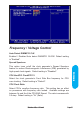
Frequency / Voltage Control Auto Detect DIMM/PCI CLK Enabled \ Disabled Auto detect DIMM\PCI CLOCK. Default setting is "Enabled". This option turns on/off the clock generator’s Spread Spectrum feature to reduce Electromagnetic Interference (EMI) generated by high speed clock signals. Default setting is "Disabled". CPU Host/PCI Clock/PC133 Select the clock generator’s Front Side Bus frequency for CPU over-clocking. Default setting is "Default". CPU Clock Ratio Select CPU’s core/bus frequency ratio.
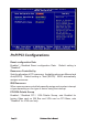
PnP/PCI Configurations Reset configuration Data Enabled \ Disabled Reset configuration Data. "Disabled". Default setting is Resources Controlled by Sets the allocation of PCI resources. Available options are Manual and Auto(ESCD). Default setting is "Auto"(ESCD). BIOS automatically assigns resources. IRQ Resources When resources are controlled manually,assign each system interrupt a type,depending on the type of device using the interrupt.
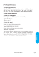
PC Health Status CPU Warning Temperature Specifies CPU warning temperature value. Available options are 50℃/122℉, 53℃/127℉,56℃/133℉, 60℃/140℉, 63℃/145℉, 66℃/151℉, 70℃/158℉ and Disabled. Default setting is "Disabled". Current System Temperature Current CPU Temperature Detect System and CPU temperature automatically. System Fan Speed CPU Fan Speed Chassis Fan speed Detect Fan Speed Status automatically. Vcore/Vft/VCC3-3/+5V/+12V/-12V Detect System's Voltage status automatically.
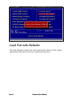
Load Fail-safe Defaults Fail-safe defaults contain the most appropriate values of the system parameters that allow minimum system performance.
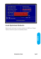
Load Optimized Defaults BIOS Setup Selecting this field loads the factory defaults for BIOS and Chipset Features which the system automatically detects.
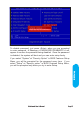
Set Supervisor / User password When you select this function, the following message will appear at the center of the screen to assist you in creating a password. Type the password, up to eight characters and press. The new password will clear the previously entered password from CMOS Memory, you will be asked to confirm the Password. Type the password again and press , you may also press to about the selection and not enter a password.
To disable password, just press when you are prompted to enter password. A Message <> will appear to confirm the password being disabled. Once the password is disabled, the system will boot and you can enter setup freely. BIOS Setup If you select "System" at "Security Option" in BIOS Features Setup Menu, you will be prompted for the password every time.
Save & Exit Setup Type "Y" will quit the Setup Utility and Save the user setup value to RTC CMOS. Type "N" will return to Setup Utility.
Exit Without Saving Type "Y" will quit the Setup Utility and Without Saving the User setup Value. BIOS Setup Type "N" will return to Setup Utility.
Glossary
Glossary PS/2 Mouse & Keyboard Connector The Mainboard provides two on-board PS/2 connectors, one for the keyboard, and one for the mouse. PS/2 devices all have a standard 6-pin round shape connector. If you are already using a PS/2 mouse or keyboard, simply plug them into the corresponding connector. No jumper settings are necessary. B ATX Power Supply Connector The Mainboard provides a single 20-pin ATX power supply connector, which incorporates standard +5V and +12V, 3.3V and soft-on/off signals.
About the Soft Touch Power Button In an ATX based system, the new soft touch power button replaces the main power switch that turns your system on and off. From an OFF state, you can switch the system ON by simply pressing the power button. From an ON state, the system can be turned OFF by pressing and holding the power button for four (4) seconds OR shut down instantly. The functions of the power button can also be altered in the Power Management section of the CMOS setup.
F Memory Module Sockets The Mainboard provides 168 pin standard DIMM sockets for installation of 3.3V unbuffered Single or Double Bank SDRAM modules. G Parallel Port Connector The ATX Mainboard provides a parallel port connector. Based on the ATX standard, a 25-pin parallel port is now built on the mainboard back panel. This design makes the mainboard installation easier.
I LITHIUM BATTERY A 3V, CR2032, Lithium battery is installed on the on-board battery socket. This battery is used to supply the CMOS RAM backup power during system powered-off. Danger of explosion if battery is incorrectly replaced. Therefore, if you have any difficulties, please consult the technical personnel. J PCI Add-In Board Connector The Mainboard provides 5 PCI Connector for the PCI cards.
Flash BIOS The Mainboard flash BIOS provides users with more flexibility in upgrading their mainboards. The flash BIOS can be easily reprogrammed via software. O Floppy Drive Header The Mainboard provides a 34-pin connector that supports the included floppy drive ribbon cable. After connecting the single end to the on-board “FLOPPY” connector, connect the remaining plugs on the other end of the cable to the corresponding floppy drives.
Q WAKEUP-LINK Header The Mainboard provides on WAKEUP-LINK header (WOL) used to connect an add-in Network Interface Card which has Wakeup capability. R Universal Serial Bus Header Connect this header to the optional USB extension cable for two USB ports. r "CNR" Add-in Board Connector Communication & Networking Riser(CNR) is a new interface standard for Networking or modem add-in card. S CPU Socket The Mainboard provides a 370-pin CPU Socket for Intel Celeron, PIII or Cyrix III processor.
T CPU / System & Auxiliary Fan Connector The recommended heatsink for the processor are those with 12 Volt three-conductor fan that can be connected to the fan connector on the mainboard. It provides +12 Volts DC to the CPU cooling fan as follows: PIN 1 2 3 SIGNAL NAME Ground +12V FAN Speed Detect CAUTION! Be sure that sufficient air circulation is available across the processor’s heatsink by regularly checking that your CPU fan is working.
V VGA Connector (Optional) Connect this connector to the VGA extension cable for integrated VGA interface (815E only). W Temperature Sensor Header The mainboard provides one header for an optional thermal sensor to monitor system temperature. X CD Audio Connector CD Audio input ( Right, Ground, Ground, Left ) Y Auxiliary Audio Connector Auxiliary input ( Right, Ground, Ground, Left ) z Case Detect If case is opened,this switch should be closed.
CD Driver & Software Installation Guide CD Driver & Software Installation Guide Steps : 1. Boot up the Operating System ( Windows 95/98/NT/2000 ) 2. Put the CD Disc into the CD-ROM Drive and wait for Autorun 3. Select A815E / A815EP and click your Operating System Type 4.