
Quick Guide
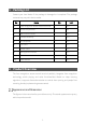
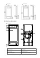
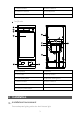
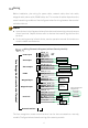
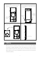
Table Of Contents

5
Wiring Schematic Diagrams (with Security Module)
Tool Preparation
•
Phillips screwdriver
•
ESD wrist strap or gloves
•
Electric drill
•
Tape measure
•
Marker
•
Silicone glue
•
Glue gun
Installation Steps
The following installation steps are the same for different models.
Determine the position of the 86*86mm junction box.
If no junction box has been buried in the wall, skip this step to step 3. The two
installation holes on the box should be parallel to the ground
during actual
installation.
RS485
LOCK_NC Yellow
LOCK_COM Purple
LOCK_NO Gray
GND Black
SEN Orange
BUTTON White
PRESS
TO EXIT
+
+
-
-
+
-
VDD12V Red
GND Black
+12V
GND
Alarm input
device
GND Black
ALM_IN Red
RS485_A
Orange
RS485_B
Yellow
485_P
Blue
485_N
Brown
Face Recognition Access
Control Terminal
Power input
Door lock
Alarm input
Door opening button
Electric strike
Door magnetic
sensor
Electric drop bolt lock
/Magnetic lock
Power
supply
Gated Security
Module