
Quick Guide
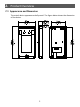
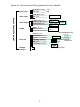
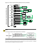
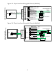
Table Of Contents

Figure 3-3 16-pin interface Wiring (with Security Module)
Figure 3-4 20-pin interface Wiring (with Security Module)
RS485_N BROWN
RS485_P BLUE
RS485
RS485_P BLUE
RS485_N BROWN
GND BLACK
+12V
GND
VDD12 INPUT ORANGE
LOCK NC YELLOW
LOCK COM WHITE
LOCK NO YELLOW/GREEN
GND BLACK
SEN_ INPUT GREEN
BUTTON INPUT PURPLE
PRESS
TO EXIT
Power
supply
+
+
-
-
+
-
GND BLACK
ALARM INPUT1 GRAY
Alarm input
device
Door opening button
Gated Security
Module
Power
input
Door
lock
Alarm
input
Anode lock/Magnetic lock
Cathode lock
Door status
switch
Access Control Terminal
Fac e Re cognition Acces s
Control T er mi n al
RS485
RS4 85 _A O RA NG E
RS4 85 _B Y ELL OW
RS4 85 _A
O RA N G E
RS4 85 _B
Y ELL OW
VDD12 V OR ANGE
GN D B LAC K
LOC K_NC Y E LL O W
LOC K_C OM WHI TE
LOC K_O N Y E LL O W/GREEN
SEN_I NP UT GREEN
GN D B LAC K
B UTT ON INP UT PU RP LE
GN D B LAC K
ALARM_INP UT1 GRAY
+
-
+
-
T O EX I T
P R ES S
Ala rm in put
d evice
Power input
Do or l ock
Alarm input
+12V
GN D
Ga ted Security
Module
A no de l oc k/M agn eti c lo c k
+ Power supply -
C at ho d e l oc k
Door statu s
s wi tc h
Door opening but ton
7