
Quick Guide
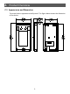
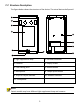
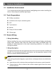
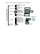
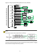
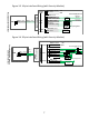
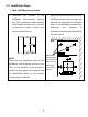
Table Of Contents

Figure 3-2 20-pin interface Wiring (without Security Module)
NOTE!
You can also connect alarm output devices as follows
:
The access control terminal can be also connected to a security module. The figure
below shows the wiring of the security module.
VDD12V RED
GND BL AC K
+12V
GND
ALM_IN1 PURPLE
GND BL AC K
ALM_IN2 WHITE/PUR PLE
Alarm inp ut device
Alarm inp ut device
ALM_OU T_NC GRA Y
ALM_OU T_CO M WHITE/OR ANGE
ALM_OU T_NO WHITE/BL UE
A lar m o utp ut
device
A lar m o utp ut
device
- Power +
sup ply
Wiegand input
RS485_A OR ANGE
RS485_B YELL OW
Digital Detection
Module
GND BL AC K
WIEGAND_IN0 BLUE
WIEGAND_IN1 WHITE
Wiegand
card reader
Acces s
controller
WIEGAND_OU T0 BR OWN
WIEGAND_OU T1 GREEN
GND BL AC K
LO CK_NC PINK
LO CK_CO M WHITE/BL AC K
LO CK_NO WHITE/GREEN
SEN_INP UT LIGHT GR EEN
GND BL AC K
BUTTON_INP UT YELL OW/BL AC K
Anode lock/Magn etic lock
Cathode loc k
+
-
+ Power supply -
Door status
sw i tc h
Door open ing bu tton
TO EXIT
PRES S
Wiegand output
Door lock
Network
int er face
RS4 85
Alarm output
Alarm input
Power input
-
Face Recognition Access Control Terminal
- Power +
sup ply
+
6