Face Recognition Access Control Terminal Quick Guide V2.
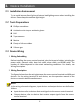
Contents 1. Packing List ............................................................................................... 1 2. Product Overview ..................................................................................... 2 2.1 Appearance and Dimension .................................................................... 2 2.2 Structure Description.............................................................................. 3 3. Device Installation ...............................................
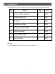
1. Packing List The attachments may vary with models, please see the actual model for details. No. Name Qty Unit 1 Access control terminal 1 PCS 2 Screw component 2 Set 3 Bracket 1 PCS 4 Installation sticker 1 PCS 5 16-pin or 20-pin cable 1 PCS 6* 10-pin terminal 1 PCS 7 2-pin power cable 1 PCS 8 User manual 1 PCS Remarks: * means optional and supplied with certain models only.
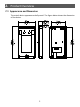
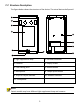
2. Product Overview 2.1 Appearance and Dimension The actual device appearance shall prevail. The figure below shows the dimension of the device.
2.2 Structure Description The figure below shows the structure of the device. The actual device shall prevail. 1 2 3 4 8 9 10 5 7 11 6 1. Light supplement lamp 2. Infrared illuminator 3. Cameras 4. Display screen 5. Card reading area 6. Reboot button 7. Microphone 8. Tamper proof button 9. 16-pin or 20-pin interface 10. Network interface 11. Loudspeaker NOTE! Certain models may have different light supplement lamp and cameras .
3. Device Installation 3.1 Installation Environment Try to avoid intense direct light and intense backlighting scenes when installing the device. Please keep the ambient light bright. 3.2 Tools Preparations Phillips screwdriver Antistatic wrist strap or antistatic gloves Drill Tape measure Marker Plenty of silicone rubber Silicone gun 3.
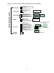
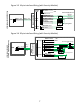
Figure 3-1 16-pin interface Wiring (without Security Module) +12V GND Alarm input device Alarm output ALARM OUT NC PINK ALARM OUT COM RED/BLUE ALARM OUT NO RED Alarm output device RS485 RS485_P BLUE RS485_N BROWN Door lock LOCK NC YELLOW LOCK COM WHITE LOCK NO YELLOW/GREEN SEN_ INPUT GREEN Power supply - Door status switch PRESS Door opening button 5 + Anode lock/Magnetic lock + TO EXIT Network interface Power supply Digital Detection Module GND BLACK BUTTON INPUT PURPLE - Alarm output
Figure 3-2 20-pin interface Wiring (without Security Module) Power input Alarm output RS485 Wiegand input Wiegand output Door lock Alarm input device Alarm input device Alarm output device ALM_OUT_NC GRAY ALM_OUT_COM WHITE/ORANGE ALM_OUT_NO WHITE/BLUE RS485_A ORANGE RS485_B YELLOW Alarm output device - Power + supply Digital Detection Module GND BLACK WIEGAND_IN0 BLUE WIEGAND_IN1 WHITE Wiegand card reader WIEGAND_OUT0 BROWN WIEGAND_OUT1 GREEN GND BLACK Acces s controller - Power + supply PRES
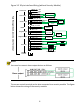
Figure 3-3 16-pin interface Wiring (with Security Module) GND Door status Cathode lock switch GND BLACK ALARM INPUT1 GRAY PRESS TO EXIT BUTTON INPUT PURPLE Alarm input - Door lock + Power supply + Anode lock/Magnetic lock LOCK NC YELLOW LOCK COM WHITE LOCK NO YELLOW/GREEN SEN_ INPUT GREEN - RS485_P BLUE RS485_P BLUE RS485_N BROWN RS485_N BROWN +12V + RS485 Gated Security Module Access Control Terminal VDD12 INPUT ORANGE GND BLACK Power input Door opening button Alarm input device GN
3.4 Installation Steps 1 With a 86*86mm junction box the 2. Align the installation sticker with the junction 86*86mm junction box and align the box. This installation mode embeds two holes B with the two installation an 86*86mm junction box in the wall holes on the 86*86mm junction box. 1. Determine 86*86mm the position wall-mounted of in advance or makes a hole on the Determine wall to embed the box. installation holes on the wall based on the the two holes A.
3. Use a drill to drill two holes with the depth of 30mm and diameter of 6mm 4. Embed expansion bolts inside the two installation holes on the wall. to 6.5mm on the wall. CAUTION! Avoid embedded wires in the wall during drilling! 5. Align holes on the bracket with installation holes on the wall and the 86*86mm wall-mounted junction box and use the Phillips screwdriver to tighten the screws clockwise to fasten the bracket. 9 6. Fasten the access control terminal to the bracket hook.
7. At the bottom of the device, use the wrench to tighten the fastening screws clockwise. 2 Without a 86*86mm junction box 1. Determine the position of installation 2. Use a drill to drill three holes with the holes on the wall based on the depth of 30mm and diameter of 6mm reference line and hole A on the to 6.5mm on the wall. installation sticker. Wall Use hole A to determine installation holes.
3. Embed expansion bolts inside the three installation holes on the wall. 4. Attach the bracket to the wall with its holes aligned with the installation holes, and then rotate the screws clockwise using a Phillips screwdriver to fasten the bracket. Wa ll 5. Refer to step 6-7 in With a 86*86mm junction box section to complete installation. 4.
5. Web Login You can log in to the Web page of the access control terminal to manage and maintain the device. For detailed operations, see the Face Recognition Access Control Terminal User Manual. 1. On a client PC, open the Internet Explorer (IE9 or later), enter the IP address of the device 192.168.1.13 into the address bar, and press Enter. 2. In the login dialog box, enter the username (admin by default) and password (123456 by default), and click Login to access the Web page.
6. Personnel Management NOTE! Only some models support personnel management on the Web interface and GUI interface. Personnel management on the Web interface On the Web interface, you can add persons (one by one or in batches), modify person information, or delete persons (one by one or together). The detailed operations are described as follows: 1. Log in to the Web interface. 2. Choose Setup > Intelligent > Face Library to go to the Face Library interface, on which you can manage personnel information.
7. Appendix NOTE! Only available for certain models. 7.1 Face Recognition Precautions 7.1.1 Face Photo Collection Requirements General requirement: bareheaded full face photo, with the front side facing the camera. Range requirement: The photo should show the outline of a person's both ears and cover the range from the top of the head (including all hair) to the bottom of the neck. Color requirement: true color photo.
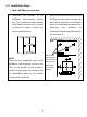
Figure 7-1 Face Match Position Note: Range of recognizable distance: 0.5m to 2m. Wall 2m Matchable range 1.5m 1m 1 2 0.5m Ground 0.5m 1m 1.5m 2m NOTE! The face match position should be within the recognizable range shown in the figure. If face match fails in area 1 shown in the figure, move backward. If face match fails in area 2 shown in the figure, move forward.
7.1.3 Face Match Posture 1 Facial Expression To ensure the accuracy of face match, keep natural expression during the match (as shown in the figure below). Figure 7-2 Correct Expression 2 Facial Posture To ensure the accuracy of face match, keep the face facing the recognition window during the match. Avoid the head to one side, side face, head too high, head too low, and other incorrect postures.
Disclaimer and Safety Warnings Copyright Statement ©2020-2021 Zhejiang Uniview Technologies Co., Ltd. All rights reserved. No part of this manual may be copied, reproduced, translated or distributed in any form by any means without prior content in writing from Zhejiang Uniview Technologies Co., Ltd (referred to as Uniview or us hereafter). The product described in this manual may contain proprietary software owned by Uniview and its possible licensors.
Uniview reserves the right to change any information in this manual without any prior notice or indication. Due to such reasons as product version upgrade or regulatory requirement of relevant regions, this manual will be periodically updated. Disclaimer of Liability To the extent allowed by applicable law, in no event will Uniview be liable for any special, incidental, indirect, consequential damages, nor for any loss of profits, data, and documents.
Enable HTTPS/SSL: Use SSL certificate to encrypt HTTP communications and ensure data security. Enable IP address filtering: Allow access only from the specified IP addresses. Minimum port mapping: Configure your router or firewall to open a minimum set of ports to the WAN and keep only the necessary port mappings. Never set the device as the DMZ host or configure a full cone NAT.
Make sure the power supply provides a stable voltage that meets the power requirements of the device. Make sure the power supply's output power exceeds the total maximum power of all the connected devices. Verify that the device is properly installed before connecting it to power. Do not remove the seal from the device body without consulting Uniview first. Do not attempt to service the product yourself. Contact a trained professional for maintenance.
Chemical Burn Hazard. This product contains a coin cell battery. Do not ingest battery. If the coin cell battery is swallowed, it can cause severe internal burns in just 2 hours and can lead to death. Keep new and used batteries away from children. If the battery compartment does not close securely, stop using the product and keep it away from children. If you think batteries might have been swallowed or placed inside any part of the body, seek immediate medical attention.
IC Statements This device complies with Industry Canada licence-exempt RSS standard(s). Operation is subject to the following two conditions: — This device may not cause interference, and — This device must accept any interference, including interference that may cause undesired operation of the device. Le présent appareil est conforme aux CNR d'Industrie Canada applicables aux appareils radioexempts de licence.
Better Security, Better World www.uniview.com globalsupport@uniview.