
Quick Guide

9
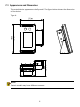
3.3 Device Wiring
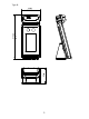
1 Wiring Embedding
Before installing the face recognition access control terminal, plan the layout of
cables, including the power cable, network cable, door lock cable, and alarm cable.
The number of cables depends on the actual networking conditions. For details,
see Wiring Description.
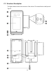
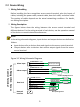
2 Wiring Description
The figures below show the wiring between the access control terminal and
different devices. For the wiring terminal of each device, see the operation manual
of the device or consult related manufacturers.
NOTE!
In the wiring schematic diagrams, input devices and output devices are defined as
follows:
⚫ Input devices refer to devices that send signals to the access control terminal.
⚫ Output devices refer to devices that receive output signals from the access
control terminal.
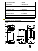
Figure 3-1 Wiring Schematic Diagrams
Power
supply
Alarm input
Alarm output
Door lock
ALARM OUT NO ORANGE
ALARM OUT NC PINK
ALARM OUT COM YELLOW/BLUE
LOCK NC YELLOW
LOCK COM WHITE
LOCK NO YELLOW/GREEN
GND BLACK
SEN_ INPUT GREEN
BUTTON INPUT PURPLE
PRESS
TO EXIT
Power supply
+
Anode lock/Magnetic lock
+
-
-
Cathode lock
+
-
Door status
switch
Door opening button
Face Recognition
Access
Control Terminal
-
+
Network
interface
GND BLACK
ALARM INPUT1 GRAY
Alarm input device
Alarm output
device
Alarm output
device