
Quick Guide

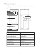
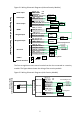
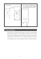
Table Of Contents

5
Figure 3-1 Wiring Schematic Diagrams (without Security Module)
The face recognition access control terminal can be also connected to a security
module. The figure below shows the wiring of the security module.
Figure 3-2 Wiring Schematic Diagrams (with Security Module)
Power input
Alarm input
Alarm output
RS485
Wiegand output
Wiegand input
Door lock
VDD12V RED
GND BLACK
+12V
GND
GND BLACK
ALARM_IN1 WHITE/BLUE
ALARM_IN0 WHITE/GREEN
ALARM_OUT_NO WHITE/ORANGE
ALARM_OUT_NC GREEN
ALARM_OUT_COM WHITE/PURPLE
RS485_P ORANGE
RS485_N PURPLE
GND BLACK
WG_IN_D0 WHITE/BLACK
WG_IN_D1 WHITE/RED
GND BLACK
WG_OUT_D0 BLUE
WG_OUT_D1 RED
+
-
LOCK_NC GREY
LOCK_COM WHITE
LOCK_NO BROWN
GND BLACK
SEN_ IN WHITE/BROWN
BUTTON_IN WHITE/ YELLOW
PRESS
TO EXIT
+
+
-
-
+
-
Face Recognition Access Control Terminal
-
+
USB2.0
Network interface
USB drive
Card
reader
Door opening button
Cathode lock
Door status
switch
Power supply
Anode lock/Magnetic lock
Access
controller
Power
supply
Wiegand
card
reader
Alarm output
device
Alarm output
device
Alarm input
device
Alarm input
device
Power
supply
Digital Detection
Module
RS485
LOCK_NC YELLOW
LOCK_COM PURPLE
LOCK_NO GREY
GND BLACK
SEN ORANGE
BUTTON WHITE
PRESS
TO EXIT
+
+
-
-
+
-
VDD12V RED
GND BLACK
+12V
GND
Alarm input
device
GND BLACK
ALM_IN1 RED
RS485_P ORANGE
RS485_N PURPLE
485_P BLUE
485_N BROWN
Face Recognition Access
Control Terminal
Power input
Door lock
Alarm input
Door opening button
Cathode lock
Door status
switch
Anode lock/Magnetic lock
Power
supply
Gated Security
Module