
Quick Guide


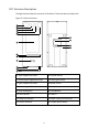
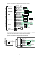
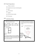
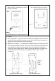
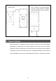
Table Of Contents

4
3 Device Installation
3.1
Installation Environment
Try to avoid intense direct light and intense backlighting scenes when installing
the device. Please keep the ambient light bright.
3.2
Device
Wiring
1 Wiring Embedding
Before installing the face recognition access control terminal, plan the layout of
cables, including the power cable (for the diameter selection for the extension
power cable, see Table 3-1), network cable, door lock cable, Wiegand cable, alarm
cable, and RS485 (RS232) cable. The number of cables depends on the actual
networking conditions. For details, see Wiring Description.
Table 3-1 Diameter Selection Table for Extension Power Cables
DC 12V/2A for power supply; the lower limit for the operating voltage is DC 9V (12V-25%)
Wire Diameter (mm)
0.8mm
1mm
1.25mm
1.63mm
(20AWG)
(18AWG)
(16AWG)
(14AWG)
Transmission Distance (m)
18
37
58
99
2 Wiring Description
The figures below show the wiring between the access control terminal and
different devices. For the wiring terminal of each device, see the operation
manual of the device or consult related manufacturers.
N
OTE!
In the wiring schematic diagrams, input devices and output devices are defined as
follows:
•
Input devices refer to devices that send signals to the access control terminal.
•
Output devices refer to devices that receive output signals from the access
control terminal.