
User's Manual

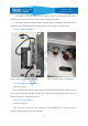


Table Of Contents
- Chapter 1 Overview
- Chapter 2 Installation
- 2.1 Installation protection
- 2.2 Unpacking inspection
- 2.3 Installation of necessary equipment
- 2.4 Antenna installation
- 2.5 Gateway body installation
- 2.6 Power supply installation
- 2.7 Grounding cable installation
- 2.8 Antenna extension scheme
- 2.9 Interface waterproofing
- 2.10 Pole and wall mounting
- 2.12 Antenna replacement
- Note:Replacement step reference to 2.4 Antenna ins
- Chapter 3 Broadcast Compliance Instructions
- Chapter 4 Precautions
- Chapter 5 Troubleshooting
- Notice to Users
- Contact Information

20
IoT Interworking
Make Your Life Smart
Security Code
1. The interface between the antenna and the gateway needs to be rotated and locked with a
flat-nose pliers, otherwise it may have a certain impact on the RF performance.
2. The direction of the GPS antenna needs to be perpendicular to the plane of the bottom plate of
the gateway, face outward and be parallel to the ground to ensure the quality of the GPS signal.
2.6 Power supply installation
Figure 7 Gateway power supply installation Figure 8 Gateway power cord installation
2.6.1 Power supply body installation
As shown in Figure 7:
Place the output socket end of the power supply upward (marked with yellow box), make it close to
the wall of the bottom plate (marked with green box), align the hole with the bottom plate screw hole
(marked with red box), and tighten the screws.
2.6.2 Power cord installation
As shown in Figure 8:
Align the notch of the power cord interface with the protruding part of the gateway power
connector (marked with red box), insert and tighten.