
Specifications

Leader in IOT Embedded Solution
Page 7 of 15
20
GND
Ground
21
GND
Ground
22
GND
Ground
23
VDD
Power supply
24
RST
Reset
25
P1_3
GPIO
26
P1_2
GPIO
27
RX
RX
28
TX
TX
29
VDD
Power supply
30
GND
Ground
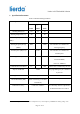
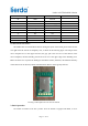
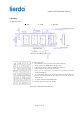
2.4 PCB antenna instructions
The module has an on-board PCB antenna. During the layout of the board, please make sure the
area right below the antenna is completely clear, as shown in the following figure. The red part is the
user’s backplane area or the copper-clad area, the grey part is the clear area of the antenna of the
user’s backplane, and the boundary point of the clear area is the upper edge of the shielding cover.
Make sure there is no any metal in 360 degrees around the antenna; otherwise, the radiation efficiency
of the antenna will be affected, and the communication distance will be greatly affected.
Drawing 2-3 Description of Clear Area of Antenna
3. Basic Operation
The module is installed on the user’s product. Since the module is equipped with MCU, it can be