
User's Manual
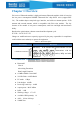
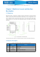
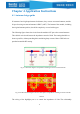
Table Of Contents

10
Chapter 4 Application Instructions
4.1 Antenna design guide
If customers have high requirements for distance, they can use an external antenna, and the
IO port for using an external antenna is PIN27 (ANT). The bottom of the module, including
the original antenna position, should be completely covered with copper.
The following figure shows the circuit from the module ANT pin to the external antenna.
The red thick wire should ensure the impedance control of 50Ω. The routing should be as
short as possible, without punching holes and taking sharp corners. More GND holes are
punched around the RF routing.
Fig. 4.1 Schematic diagram of impedance matching circuit for external antenna
Fig. 4.2 PCB schematic diagram and route description of impedance matching circuit for external
antenna
The wiring of the highlight part is to control the impedance of 50Ω. The relationship