
Specifications
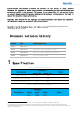

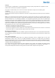
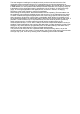

BW
PL
2
SF
125kHz
5
255 bytes(136ms
)
6
255 bytes(229ms
)
7
255 bytes(394ms
)
8
255 bytes(696ms
)
9
255 bytes
(1250ms
)
10
Not supported
11
Not supported
12
Not supported
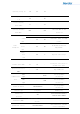
3.2 Hardware layout considerations
1. 1. DIO port as far as possible to connect to the MCU with external interrupt IO port.
2. 2. The RF exit to the antenna pad part of the alignment as short as possible, to go 50Ω impedance
line, and need to wrap the ground, the alignment around the more perforated.
3. 3. If possible, add π circuitry from the RF exit to the antenna pad.
4. 4. The antenna should be surrounded by clear space, leaving at least 5mm of clear space. 5.
5. 5. Pay attention to a good amount of grounding, preferably ensure a large area of grounding.
6. 6. Keep away from high voltage circuits, high frequency switching circuits.
7. can refer to the application document "RF PCB LAYOUT design rules (for sub-1GHZ and
Bluetooth modules)" for layout and routing.
3.3 Software operation
By inserting the module on the user's board, using the microcontroller to communicate
with the module via SPI, and manipulating its registers and transceiver cache via API commands,
the wireless data transmission and reception function can be completed. Please refer to the
latest LLCC68 data sheet for the timing of the module register read/write operations.
T
he API instructions are detailed in the LLCC68 datasheet and the corresponding API instruction
functions are provided in the Lierda demo routines.
4 Frequently Asked Questions
4.1 Modules cannot communicate even at close range
· Confirm that the configuration of the transmit and receive sides do not match, different
config
urations do not communicate properly.
· Voltages are abnormal, low voltages can lead to transmission abnormalities.
· Low battery, low battery voltage will be pulled down when transmitting causing a
PL indicates the recommended maximum packet length or the time required to transmit the next packet of that packet length (calculated as CR=4/5, Preamble length is
8 symbol); "not supported" means that the LLCC68 chip itself does not support this configuration.