
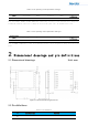
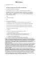
Specifications


P2
DIO1 Interrupt source mapping pins (see LLCC68 datasheet
for details)
P3
DIO2
Interrupt source mapping pins (see LLCC68 datasheet
for details)
P4
BUSY Line Occupancy Indicator
P5
SW_CTL2
RF switch control pin 2,TX:SW_CTL1=0,SW_CTL2=1
RX:SW_CTL1=1,SW_CTL2=0
Sleep:
SW_CTL1=0
,
SW_CTL2=0
P6
SW_CTL1 RF switch control pin 1,TX:
SW_CTL1=0,SW_CTL2=1
RX
:SW_CTL1=1,SW_CTL2=0
Sleep:SW_CTL1=0,SW_CTL2=0
P7
GND Power ground
P8
VCC
Power supply VCC
P9
MISO SPI data output
P10
MOSI SPI data input
P11
NSS Chip SPI enable
P12
SCK SPI clock input
P13
GND
Power ground
P14
RF
RF output
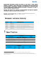
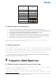
3 Basic operation
3.1 Packet size selection
The maximum packet byte setting can support 255 bytes. Considering the actual usage, a packet
with a larger number of bytes will last longer in the air and be susceptible to interference,
especially at low rates which may have a greater impact, and this module may even fail to
communicat
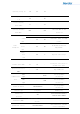
Table 3-1 FL22-22 LoRa mode supported rate configuration and recommended maximum packet length