
User's Manual
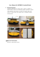
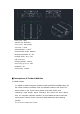


Table Of Contents

In the power management module, commands for powering on and off robots can
be obtained through wireless module. If a command for powering on robot is
received, the power management module will switch on the power supply and
power on all devices. When a command for powering off robot is received, the
module will switch off the power supply and power off all devices. Meanwhile, all
other devices will be switched to standby states with low power consumption
except for the power management module.
3.2. Chassis module
Realize the detection of RFID(13.56MHz) code and location information
detection, and upload. The data to the BMSP module through CAN communication.
3.3. Switching power module
Voltage conversion from 4.6V to 24V is under the control of the power
managementmodule,And protect the battery from overvoltage due to charging
3.4. Battery Pack and Charging Port
The battery pack is made of two 2.3V lithium batteries connected in series. The
robot must be charged using special charging piles. The maximum charging current
is 90A.
3.5. Servo Modules
At present, a robot has four servo modules, including left wheel, right
wheel ,front crossbeltand rear crossbelt,Used for walking control and unloading
control
3.6. Buttons and LED Indicator Lights
Buttons are utilized for testing single robots and manually controlling shutdown.
The LED indicator light is employed for indicating current state.
The functions of buttons and the indicator lights are shown as follows: