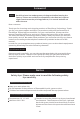
EN/CN-A02 WARNING Foto 13.3 1. When the glass over the LCD screen cracks, stop printing immediately, otherwise the crack will expand and cause more serious damage. 2. The maximum tank volume is 3 liters. Note that moderate resin must be added so its level will be between the upper and lower marker lines in the tank. 3. The correct way to cut off power supply is to turn off the power switch of the printer. 4. Do not cut off the power abruptly during printing to avoid mechanical damage.
NOTE Three screws A, B and C indicated in the picture should not be loosened, otherwise the printing will fail! 01
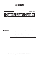
Foreword Note Each 3D printer has undergone a printing test before leaving the factory. If there are residual consumables in the feed resin tank or slight scratches on the printing platform, it is normal and will not affect the use. Dear customer: Thank you for choosing and using the products of Flashforge Technology. Thank you for your great support and help. The product quality and performance of Flashforge Technology are excellent.
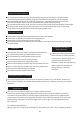
Electrical Requirements Be sure to ground the device; do not modify the plug of the device. (Ungrounded/ incorrectly grounded/modified plugs will inevitably increase the risk of leakage) Do not expose the device to humidity and hot sun. (Wet environment will increase the risk of leakage/exposure will accelerate the aging of plastic parts) Do not abuse the power cord, and be sure to use the power cord provided by Flashforge. Do not use the device during thunderstorms.
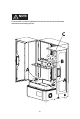
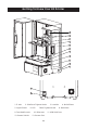
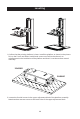
Getting To Know Your 3D Printer 1 2 3 4 5 6 7 8 9 10 11 12 13 1. Z-axis 2. Platform Tighten Knob 5. Light Shield 9. Touched Screen 12. Power Switch 6. LCD 3. Leveller 7. Box Tighten Knob 10. Ethernet 13. Power Slot 04 4. Build Plate 8. Resin Box 11.
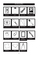
Accessory Box 3D Printer Resin Power Cable Quick Start Guide After-sales Service Metal Scraper Plastic Scraper Brush Rubber Glove USB Stick Wrench Accessory Kit Tweezers Soft Cloth Filter Diagonal Pliers 05
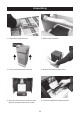
Unpacking 1. Cut the tie to open the box. 2. Take out the top foam. 3. Lift up and remove the outer box. 4. Remove the foam on both sides. 5. Open the front door of the device and prepare to take out the foam inside. 6. Loosen the platform fastening knob.
7. Take out the molded platform. 8. Remove the foam. Note that there is a bottle of resin and a tool box inside the foam cotton. 9. Complete.
Leveling 1. Confirm that the printing platform is clean. Install the platform as shown in the picture: fit it on the Z-axis and fasten it with hand-screw nuts.Confirm that there is no misalignment in the installation of the platform and that it is not loose when moved manually. Loosen Loosen 2. Loosen the four M6 screws in the upper-adjustment block of the platform assembly. Note that there are two screws on the both sides of the upper adjustment block.
3. Connect the power cable to theadapter, insert the outputof the power adapter into the power inlet port on the back of the printer. Turn on the switch. Print Tool System Move Residue WLAN Stop 4. Place 3 sheets of A4 paper over the printer screen. 5. Click on [Tools] in the main interface, and then click on [Z-axis Move].
Z: 22 - 00 mm + Stop No.2 No.4 No.3 Tighten No.1 6. Click on [Reset] to reset the Z-axis and lower the platform to the zeroposition. When the platform is lowered to the bottom, tighten the four M6 screws No.1-4 in sequence according to the figures shown. Z: 22 - 00 mm + Stop 7. Pull the A4 paper back and forth. Make sure some resistance can be felt during pulling. 8. Click on "+" to raise the platform 200-300 mm to complete the leveling.
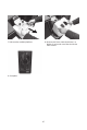
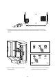
First Printing 1. Confirm that the LCD screen and resin box are clean. 2. Take out the resin box and place it carefully on the screen. Pay attention to the orientation of the pouring port and install it in the direction shown on the right. 3. Tighten the screws on both sides.
No misalignment and looseness in installation Clean 4. Confirm that LCD screen, build plate and solution box are clean. 5. Make sure that the resin box and platform are installed in alignment and that they are not loose when moved by hand. 6. Shake the resin to mix itwell. 7. Pour the resin into the solution box. Note that level shall not exceed or be lower than the mark lines in the resin box. Close the light shield after all above preparatory steps.
File list Model-01 Model-02 Print Tool System Model-03 Model-04 Model-01 1000 3 h 49 min 0.05 mm 9. Click [Print] to enter the model list. Click the model file to start printing.
Post-processing 1. When the printing is finished, a notification will be displayed.Click [OK], open the light shield, take out the build plate, drain the remaining resin, and shovel the model off with a scraper. Note: There will be uncured resin on the model when printing is just finished. Please note that the model must be dried before being processed. 2. Small models are cleaned in an ultrasound device filled with alcohol, while the large models are rinsed in a drum with alcohol. 3.
Replace the FEP film in the resin box 1. Loosen the screws indicated in the picture and take out the resin box. Remove the remaining resin and clean the box. 2. Turn the box up side down and loosen the screws on the base. Take out the FEP membrane module to be replaced. 3. Clean the bottom of the resin box and the screws, and prepare a new module. Note: Do not touch and leave fingerprints on the membrane which will affect printing. 4. Place the FEP membrane at the bottom of the resin box. 5.
05 02 03 04 09 08 07 10 06 01 6. Tighten the M4*12 countersunk screws from 1 to 10. Please do it in a diagonal order. 7. Cut off excess FEP membrane (dark part) to finish the replacement. Please double check if the resin box is polluted with dirt, fingerprints, etc. If so, it needs to be cleaned again.
Software Operation FlashDLPrint Load FlashDLPrint.exe Print Set Position Move X: 0.00mm Y: 0.00mm Z: 0.00mm Print 2. Click Load, select the model file. 1. Install and run the FlashDlprint.exe program. View Supports I want to: Material Type: Save As New Operation: Layer Height: Print When Slice Done Preview Grey Standard Remove 0.1mm More Options >> Exposure Time Rotate On Platform Separately Scale On Platform Raft Size Adjust Base Time: 5.5s Attach Time: 80.
CHITUBOX CHITUBOX V1.8.1 Open Project 1. Install and turn on the ChiTuBox64.exe program. Save ProJect Open... Save As... 2. Click the【Open...】in the menu at the upper left corner to select the model files. untitled* CHITUBOX V1.8.1 File List Select All Solid X-Ray X: 0.00 Y: 0.00 Z: 0.00 X: +90° -90° 0.00 Y: +90° -90° 0.00 Z: +90° -90° 0.00 Slice Put on the plate Flatten by face Centered Reset Reset Z Y Settings X 3.
Settings FLASHFORGE Standard Resin Grey for 0.1mm Default Machine Resin Print Gcode Advanced foto 13.3 foto 8.9 foto 6.0 Layer Height: 0.1 mm Bottom Lift Distance: 10 mm Bottom Layer Count: 1 Lifting Distance: 10 mm Exposure Time: 8 Bottom Lift Speed: 65 mm/min Lifting Speed: 65 mm/min Retract Speed: 150 mm/min Exposure Time: Linear 6 s 80 s Light-off Delay: 0 s Bottom Light-off Delay: 0 s Exposure Time: Bottom Exposure Time: 4.
Maintenance Please keep two parts shown in the picture below clear without dust and fingerprint. Do not pour the used residual resin back to the resin bottle. The waste resin can be poured into the sealing bag for sealing and then be exposed to the sun until the resin solidifies. If the print doesn’t work for quite a long time, please pour the residual resin in the resin box into a closed container and keep it away from light.
Follow us Zhejiang Flashforge 3D Technology Co., Ltd. Address: No.518 XianYuan Road, Jinhua City,Zhejiang Province, China Service Hotline: +86 579 82273989 support@flashforge.
FCC Statement This device complies with part 15 of the FCC rules. Operation is subject to the following two conditions: (1) this device may not cause harmful interference, and (2) this device must accept any interference received, including interference that may cause undesired operation. Changes or modifications not expressly approved by the party responsible for compliance could void the user's authority to operate the equipment.