NAVIGATOR X1100 User’s Manual V1.0.0 ZHEJIANG DAHUA VISION TECHNOLOGY CO.
Legal Statement Copyright © 2018 ZHEJIANG DAHUA VISION TECHNOLOGY CO.,LTD. All rights reserved. Any or full contents of the user’s manual cannot be copied, transmitted, distributed, partially or wholly, by any means, without the prior written notice of ZHEJIANG DAHUA VISION TECHNOLOGY CO.,LTD. Dahua or the third party may reserve the right of the product described in this user’s manual.
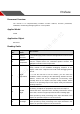
Preface Document Overview The manual is to comprehensively introduce function features, structure parameters, installation, dismounting and flight guide etc. of the product. Applied Model X1100 Application Object End users. Reading Guide Chapter No. Chapter Name Main Content 1 Product Overview It is to introduce the function features and application scenarios of the product. 2 Product Component It is to comprehensively introduce main components of the product.
6 Upgrade It is to introduce upgrade methods and points of attention. 7 Appendix 1 It is to introduce the technical parameters. 8 Appendix 2 It is to introduce the indicator definition of the aircraft. 9 Appendix 3 It is to introduce the matching method among the components. 10 Appendix 4 It is to list possible problems and solutions when using the product.
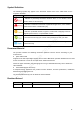
Symbol Definition The following symbol may appear in the document. Please refer to the table below for the respective definition. Symbol Note It indicates a potentially hazardous situation which, if not avoided, could result in death or serious injury. It indicates a moderate or low level of potential danger which, if not avoided, could result in minor or moderate injury. It indicates a potential risk that, if ignored, could result in damage to device, degraded performance, or unpredictable results.
Important Safeguards and Warnings The following description is the correct application method of the device. Please read the manually carefully before use, in order to prevent danger and property loss. Strictly conform to the manual during application and keep it properly after reading. Please operate the aircraft in the environment which meets flight conditions, and keep away from no-fly zone. After unlocking, operators shall keep at least 5m away from the aircraft.
Keep away from no-fly zone; please do not enter no-fly zone. Keep view wide open; make sure the device is flying within field of view; please do not block field of view. Please do not fly the aircraft in rain, snow and thunder weather. Please do not fly in narrow and small space. Try not to fly right above the crowd, in order to prevent personal injury. Please do not get close to high-voltage power line. Keep more than 10m distance.
Please do not dismantle and destroy the battery without permission; water is not allowed to enter the device; man-made damages are not covered by warranty. Please do not throw the battery into fire or expose it to high-temperature environment. Please do not dismantle, modify or deform the battery. Avoid short circuit between positive and negative contacts (please do not place the battery together with the objects such as necklace and hairpin etc.
measures: —Reorient or relocate the receiving antenna. —Increase the separation between the equipment and receiver. —Connect the equipment into an outlet on a circuit different from that to which the receiver is connected. —Consult the dealer or an experienced radio/TV technician for help. FCC RF Radiation Exposure Statement: This equipment complies with FCC radiation exposure limits set forth for an uncontrolled environment.
updates might cause some differences between the actual product and the Manual. Please contact the customer service for the latest program and supplementary documentation. There still might be deviation in technical data, functions and operations description, or errors in print. If there is any doubt or dispute, please refer to our final explanation. Upgrade the reader software or try other mainstream reader software if the Guide (in PDF format) cannot be opened.
Table of Contents Legal Statement ....................................................................................................................................... I Preface ..................................................................................................................................................... II Important Safeguards and Warnings ..................................................................................................... V 1 Product Introduction ..................
3.8.1 Remote Control Calibration .............................................................................................. 43 3.8.2 Accelerometer Calibration ................................................................................................ 43 3.8.3 Initialization Failure ........................................................................................................... 44 3.8.4 Geomagnetic Abnormity .................................................................................
Appendix 4.4 FAQ and Solutions of Charger....................................................................................
1 Product Introduction 1.1 Overview This product is a hex-rotor drone designed for public security, transportation, firefighting, border defense, agriculture, forest and energy source fields. It provides integrated solutions of aerial video surveillance. This product consists of aircraft, airborne device and remote control. Aircraft: It consists of navigation system, flight control system and power system. Airborne device: It consists of the PTZ control system and mission device.
effect. IR thermal camera is optional, suitable for special environments such as fire scene or night environment, so as to guarantee clear video and high restoration thermal images. The remote control has snapshot button and record button, which are easy to operate and instantly start snapshot and record function. Accurate Positioning Built-in GPS system ensures that positioning is accurate and real-time. Wireless Transmission Aircraft has 4 antennas.
Support customized e-fence settings.
2 Structure This product mainly consists of aircraft, airborne device and remote control. This chapter introduces the structures of these 3 components. The detailed operations will be introduced in “3Flight Preparation”. All figures listed below and all dimensions listed here for reference only. The figure and the dimensions may be slightly different from the user data due to measurement position, measurement accuracy and position indication. Please refer to the actual product for detailed information.
Figure 2-2 5
2.1.2 Structural Component Figure 2-3 No. Name Function 1 Propeller High-speed revolution to turn the brushless motor power to propulsive force. There are 3 pairs of propellers (3 CW propellers and 3 CCW propellers) with different structures. Please install propellers according to the actual situation. 2 Arm Fold and unfold. 3 Protective propeller 4 cover Battery buckle of Fix the horizontally unfolded arm. Dismantle and install the battery.
No. Name 5 Power switch indicator) 6 Empennage Built-in GPS and electronic compass. Antenna Fold or unfold. 2 antennas are to receive the remote control signal. 2 antennas are for wireless image transmission. 8 Motor control panel indicator Display red and green. Two adjacent indicators are normally on in red; their middle part indicates aircraft nose. Four adjacent indicators are normally on in green; their middle part indicates aircraft tail. 9 Motor Drive propeller rotation.
2.2.1 The 2 MP Visible Light PTZ Camera Unit is mm.
Figure 2-5 9
2.2.2 Structural Component of 2 MP Visible Light PTZ Camera Figure 2-6 No. Name Function 1 Shock absorber ball 2 Shock absorber board Reduce PTZ camera vibration during the flight, to get clearer video. 3 Installation screw Secure the PTZ camera on the aircraft. 4 Course motor 5 Course rotation arm 6 Roll motor 7 Roll rotation arm 8 Pitching motor 9 Camera 10 Lens Control horizontal direction of the camera. Control horizontal inclination angle of the camera.
2.3 Remote Control 2.3.1 Dimensions Unit is mm.
Figure 2-8 2.3.2 Structural Component Front panel, side panel and rear panel of the remote control are shown in Figure 2-9, Figure 2-10 and Figure 2-11.
Figure 2-9 No. Name Function 1 Antenna Establish the remote control relationship with the aircraft and receive images. One silver antenna is installed in the middle, while two yellow antennas are installed at both sides. 2 Hanger Fix the hanger belt. 3 Left joystick 4 Touch screen 5 Landing button 6 Battery indicator Each bar represents 25% battery power. 7 Charging indicator Indicator light is on when connecting power to the charging port. Red light is normally on: charging.
No. Name 10 Right joystick Function control Control the aircraft flight state. Table 2-3 Figure 2-10 No. Name Function 11 PTZ course scroll wheel Control horizontal shooting angle of camera lens. 12 Snapshot Press this button shortly to snapshot present image. 13 Flight mode lever 3-level lever to select flight mode. Upper level: intelligent flight mode. The aircraft flights automatically according to the specified course. Middle level: flight at the specified height.
No. Name Function Insert micro SD card: The micro SD card with the chip is facing down. Insert the card to the slot horizontally. Remove micro SD card: Press micro SD card inwards, so micro SD card pops up a little bit, and can be pulled out. 18 SD slot 19 Power port Input DC 12V power. 20 PTZ mode lever 2-level lever. It is to select PTZ mode. Upper level: Course following mode. The PTZ camera angle changes with aircraft flight direction. Lower level: Course locking mode.
No. Name Function 25 Zoom out button Press it for a short time, to zoom out the camera. Press it for a long time, to zoom out until the camera reaches the minimum magnification. Table 2-5 2.3.3 Buttons Refer to Chapter 4 for the joystick and flight mode lever button information. 2.3.3.1 Scroll Wheel Besides “PTZ Course Scroll Wheel” and “PTZ Pitching Scroll Wheel” of remote control, control PTZ “PZT Center” and “PTZ 90°” through “State Bar > Quick Operation > PTZ”. Please refer to “3.6.5.
2.3.3.2 PTZ Mode Lever Shooting direction of PTZ camera is controlled with PTZ mode lever, as shown in Figure 2-14. Figure 2-14 2-level lever: Upper level: Course following mode. Shooting angle of PTZ camera changes with aircraft flight direction. Lower level: Course locking mode. No matter what the aircraft flight angles are, the PTZ camera always faces the same degree to shoot. Lever returns to the center: start from any position, move the lever for three times continuously.
Snapshot: Press snapshot button for a short time to snapshot the present image. Record: Press record button for a short time to begin recording video. Press it for a short time again to stop recording. 2.3.4 Operation Interface After turning on with the remote control, enter main interface. It consists of the following function modules, as shown in Figure 2-16. Figure 2-16 Slide up at any position on the preview interface to hide the setting menu, function bar and state bar.
2.3.4.1 Function Setting and State Bar Figure 2-17 Icon Name Function Settings Click this icon to enter setting menu. Please refer to “1 Setting” for details. Display present PTZ mode (PTZ locking or PTZ following mode). : When the PTZ lever is at the lower level, the PTZ camera has locked the course direction. No matter how aircraft angle changes, the PTZ camera is still facing the same direction to shoot.
Icon Name Function aircraft display present aircraft battery percentage after pairing connection. Quick operation Click this icon to enter quick entry interface, and set dashboard, PTZ, image transfer and other quick options. Please refer to “3.6.5 Set Quick Operation” for details. Table 2-7 3.3.4.1.1 Setting Click to enter setting interface, as shown in Table 2-8.
Level 1 Menu Level 2 Menu Level 3 Menu Function - Set photo size. Please refer to “4.5.4.1 Photo Settings” for details. - Set relevant parameters of video. Please refer to “4.5.4.2 Video Settings” for details. Advanced Image settings Set brightness, contrast, saturation, sharpness and gamma value. Please refer to “4.5.4.3 Image Settings” for details. Aircraft firmware upgrade - Check firmware status and upgrade. Please refer to “6.1 Firmware Update” for details.
On settings interface, click to return to the previous menu and click to exit settings. 3.3.2.1.1 Locking Mode Click it to select locking mode of the aircraft on the popped up dialog box, as shown in Figure 2-18. Figure 2-18 3.3.2.1.2 Flight State List Click the icon to display drone state list, as shown in Figure 2-19. Figure 2-19 View drone state info in a real-time way. 3.3.2.1.3 Quick Operation Realize quick setting of dashboard, PTZ, image transfer and others. Please refer to “3.6.
Figure 2-20 2.3.4.2 State Display Bar Figure 2-21 Icon Name Function Aircraft direction and camera lens direction Blue triangle: it indicates the aircraft direction on the geographic position. Display remaining flight time of the aircraft. It displays N/A when the aircraft is not connected. Battery time This estimated value is for reference only. Actual flight time may be affected by enviroment and etc., so it may be different from the actual flight time.
Icon Name Function Horizontal speed Horizontal forward and backward speed of the aircraft. It displays N/A when the aircraft is not connected. Vertical speed Vertical ascending and descending speed of the aircraft. It displays N/A when the aircraft is not connected. Altitude Relative altitude from the takeoff position. It displays N/A when the aircraft is not connected. Distance from the HOME Distance between the aircraft and Home. This value is planar projection distance. Table 2-9 2.3.4.
2.3.4.3.2 Map Preview Mode Figure 2-23 In this mode, the image transmitted by the camera to the remote control is displayed in a small window at the top left corner of the preview interface. In this mode, the large window displays aircraft position on the map. Buttons in map preview mode are described as follows: Map direction locking button: When it is unlocked, press the map interface with two fingers to rotate the map; when it is locked, map direction cannot be changed.
2.3.4.4.2 Locking Mode Click the icon to select locking mode of the aircraft on the popped up dialog box, as shown in Figure 2-25.
3 Flight Preparation This chapter elaborates complete flow before the aircraft is unlocked and takes off. Please select operation according to the actual situation after the first flight is over, if it is not the used for the first time. Please operate by strictly conforming to the steps described in this chapter; the operation sequence can't be reversed.
Please refer to “3.3 Charging” when the battery is low. Please implement the sebsequent steps after charging. 4.2.1 Aircraft 3.2.1.1 Aircraft Battery Check Short press the aircraft battery switch and check the state of indicator lights, as shown in Figure 3-2. Figure 3-2 Battery switch has 5 indicator light states. The front red indicator light means that the battery is on, whereas the other 4 green indicator lights represent remaining power of the battery.
3.2.2 Remote Control 3.2.2.1 Remote Control Battery Check Move the power switch to the arrow location; view the number of indicator lights which are on. Figure 3-3 Figure 3-4 At normal temperature, the remaining power shall be ≥2. Remaining power shall be ≥3 when the temperature is lower than -10℃. 3.2.2.2 Remaining Power of Remote Control There are two statuses for each indicator light of remote control, which are normally on and off.
3.3 Charging It doesn't need to implement the following chapter if the remaining power is enough. 3.3.1 Aircraft Battery Charging During charging of power battery, charging is completed when the charger displays “FULL” and beeps. Don’t take down batteries before charging is completed. The entire charging period (from 0 to full) is about 2 hours. Charging period is related with remaining power and charging current.
Figure 3-6 Step 8 After charging is completed, disconnect it from the power socket, and then press stop button on the charger to turn off the charger. 3.3.2 Remote Control Charging The entire charging period (from 0 to full) needs approximately 3.5 hours. Please charge the remote control when its power is off. Step 1 Connect DC: connect the remote control and power adapter with a charging cable. Figure 3-7 Step 2 Connect AC: connect power adapter with AC power (AC 100V- AC 240V).
Please refer to actual product. Please implement demounting step first and then connection step when the PTZ camera needs to be replaced. It only needs to implement demounting step when the aircraft flies directly without PTZ camera. 3.4.1 Dismantle PTZ Camera Step 1 Hold 2 handles of the PTZ camera with both hands and pull them downwards, as shown in Figure 3-9. Figure 3-9 Step 2 PTZ camera is separated from the aircraft, so it is dismantled quickly. 3.4.
Step 2 Push the PTZ camera upwards quickly, so PTZ installation is completed. 3.5 Prepare Aircraft 3.5.1 Unfold Arm Unfold the arm to horizontal position. Hold the arm with left hand, and tighten helical casing with right hand, so as to fix the arm horizontally, as shown in Figure 3-11. The subsequent steps can be implemented only when the arm is fixed horizontally. Please contact our company if the arm is loose. Figure 3-11 3.5.
3.5.3 Install Aircraft Battery After battery has been installed, battery buckle shall be fixed. Then, the aircraft can be moved with battery handle. If battery buckle is not fixed, the aircraft will fall off. Step 1 Open the battery buckle, as shown in Figure 3-13. Figure 3-13 Step 2 Put the battery into battery compartment horizontally, as shown in Figure 3-14. Figure 3-14 Step 3 Close the battery buckle, and aircraft battery installation has been completed. 3.6 Prepare Remote Control 3.6.
The following chapter is optional for operation. It is for your reference when the user needs to install micro SD card. Micro SD card needs to be configured on your own. Micro SD card supports max. 16G. Figure 3-15 Make the metal surface of micro SD card face downward and insert it into the micro SD card slot of the remote control side panel horizontally. 3.6.2 Open Antenna Open the antenna of remote control to proper location, as shown in Figure 3-16. Figure 3-16 3.6.
Figure 3-17 3.6.4 Confirm Remote Control Mode It is mode 2 by default. Please set in “Settings > RC Settings > Joystick Mode” to switch mode, as shown in Figure 3-18. Figure 3-18 Please refer to “4.2.4 Manual Flight Control” for remote control mode and its corresponding relations. 3.6.5 Set Quick Operation Click at the upper right corner of main interface, set quick operation items of remote control interface, view dashboard, and set PTZ, image transfer, flight task, flight path and stop beep. 3.6.5.
Figure 3-19 3.6.5.2 PTZ Set the PTZ, such as PTZ position and throwing. Step 1 Click “PTZ”, and the system enters “PTZ” interface, as shown in Figure 3-20.
Figure 3-20 Step 2 Set parameters according to actual needs. Please refer to Table 3-3 for details. Parameter Note PTZ Mode View present mode of PTZ. PTZ Position Set PTZ position, including PTZ 90 degrees and PTZ center. PTZ 90 degrees: the camera is vertically downward. PTZ center: the camera lens faces the front. Throwing Set throwing, including throwing device A and throwing device B. Table 3-3 Click key A on the remote control, to carry out PTZ control. 3.6.5.
Figure 3-21 Step 2 Select resolution ratio, frame rate and maximum bandwidth of preview image according to actual needs. 3.6.5.4 Other Set the flight task, flight path and stop beep here. 3.6.5.4.1 Fly Task Set the flight task of remote control according to actual needs, including flight path and flight time. Step 1 Select “Other > Flight Task”. The system displays “Flight Task” interface, as shown in Figure 3-22.
Figure 3-22 Step 2 Configure flight task according to actual needs. Append: click this icon to enter waypoint setting interface, set waypoint flight task according to actual needs and save it. Download: click this icon to download present saved flight path automatically. Modify waypoint according to actual needs and save the task at remote control. Select: click this icon to select one task or multiple tasks, and delete the task. 3.6.5.4.
Figure 3-23 Step 2 Click “Edit”. Select the flight path which shall be deleted and saved according to actual needs, as shown in Figure 3-24. Figure 3-24 Step 3 Click “Complete” to complete flight data setting. Click “Select All” to operate all flight data together.
3.7 Enable Aircraft Power After power on, when the remote control doesn’t require other operations, please always keep the aircraft horizontal and static; otherwise, it may result in initialization failure. The battery is full if 4 indicator lights are green. Insert intelligent battery of the aircraft, short press power switch, and green indicator light indicates present battery electricity, as shown in Figure 3-25. Figure 3-25 3.
3.8.1 Remote Control Calibration If it isn’t turned to maximum value end, it may not respond to operation, operation is not smooth, and the aircraft may even explode after calibration. Step 1 Select “Settings > Remote Control Settings> Joystick Calibration”. The system displays “Joystick Calibration” interface, as shown in Figure 3-26. Step 2 Step 3 Step 4 Step 5 Step 6 Figure 3-26 Move both the left and right joysticks back to the middle. Click “Start Calibration”.
Figure 3-27 Place the aircraft on a flat surface, and click “Start Calibration”. The remote control will prompt “Calibration Success” if it is successfully calibrated. The remote control will prompt “Calibration Failure” if it fails to calibrate. Click “Retry” till it is successfully calibrated. Pay attention to levelness and perpendicularity during calibration. Non-standard posture during calibration will lead to abnormal flight and even explosion. 3.8.
3.8.4 Geomagnetic Abnormity Abnormity Prompt Aircraft indicator ●●● flashes. Remote control prompts “Geomagnetic Abnormity”. Possible Reasons The use position has changed a lot, which means the geographical location is quite far away from the last geographical location where the aircraft is used, causing big change to geomagnetic field. There is another intensive magnetic field or abrupt change in the environment, affecting geomagnetic field.
Figure 3-29 Step 4 Keep the aircraft vertical and rotate it for 360°vertically, as shown in Figure 3-30.
It will prompt geomagnetic calibration success if it is successfully calibrated. It will prompt geomagnetic calibration failure if it fails to calibrate. Repeat Step 2, 3 and 4 to calibrate again. 3.8.5 GPS Satellites Insufficiency Abnormity Prompt Displayed number of satellites of remote control is less than 6. GPS HDOP: at the top status bar of remote control is less than 1 bar or there is no signal.
Figure 3-32 48
4 Enable Flight This chapter will elaborate the complete flow of formal takeoff and landing of the aircraft. Please stay away from the rotating propellers or motor, to avoid personal injury. For your personal and property safety, please make sure to check the following items carefully before enabling flight. Flight preparations listed in Chapter 3 are all completed. All the components have been correctly and stably installed. Make sure that each spare part is in good condition.
Figure 4-2 Three-level driving lever: Upper level: Intelligent flight mode. The aircraft will fly automatically according to the pre-set flight route. Medium level: It is the fixed height flight mode in manual flight mode. The aircraft will maintain the current flight height when the throttle joystick is in the middle. Lower level: Fixed point flight mode in manual flight mode. The aircraft will maintain the current location when all sticks are located in the middle. 4.2 Manual Mode 4.2.
Figure 4-4 If there is obvious difference about rotating speed of the propellers, move the left joystick to lower left and meanwhile move the right joystick to lower right (or move the left joystick to lower right, and meanwhile move the right joystick to lower left), and then keep the status till the propellers stop rotating. Turn off the aircraft and contact our company. The aircraft will be automatically locked if it stays on the ground and doesn’t take off within 10s after it is unlocked. 4.2.
Figure 4-5 4.2.4 Manual Flight Control Set remote control mode and control flight direction of the aircraft. Figure 4-6 The joystick presets two remote control modes. It is mode 2 by default. Please modify in “Settings > Remote Control Settings > Joystick Mode” to switch to mode 1. Mode 1: Vertical direction of left joystick is pitching joystick, which controls the aircraft to go forward and backward horizontally.
make left and right turn horizontally. Vertical direction of right joystick is throttle joystick, which controls the aircraft to ascend and descend. Horizontal direction of right joystick is rolling joystick, which controls the aircraft to move left and right horizontally. Figure 4-7 Mode 2: Moving the left joystick up and down (throttle joystick) to control aircraft’s ascending and descending.
Figure 4-9 4.2.6 Manual Locking Move the left joystick to lower left and move the right joystick to lower right at the same time (or move the left joystick to lower right and move the right joystick to lower left at the same time).
4.3 Intelligent Mode 4.3.1 Intelligent Flight Mode Intelligent flight mode includes waypoints and circle around point of interest. Waypoints flight: Set waypoint flight mission according to requirements. Move the flight mode joystick at right rear of remote control to intelligent mode after the aircraft takes off, select proper flight mission and click “Start Mission”. Circle (around point of interest) flight: Set circle flight mission according to requirements.
4.3.1.1 Waypoints Step 1 Select “Waypoints”. The system displays “Waypoints” interface, as shown in Figure 4-12. Check total route length, estimated flight time and set “Cycle Flight” at the bottom of the interface. Figure 4-12 Step 2 Click the map and the position can be set as a waypoint; several waypoints can be connected together and form a route. Check total route length, estimated flight time and set “Cycle Flight” at the bottom of the interface. Step 3 Click a waypoint and it will become red.
Figure 4-13 Step 4 Set waypoint parameters. Please refer to Table 4-1 for more details. Parameter Note Altitude Set flight altitude of waypoint. Speed Set flight speed of waypoint Head orientation Set head orientation of waypoint according to requirement during flight. Residence time Set hovering time after the aircraft reaches a waypoint. Latitude longitude and Waypoint action Action cycle Automatically acquire latitude and longitude of the waypoint when adding the waypoint.
in the list. Click to enter flight mission interface. There are three operations: Add mission: Click the icon to enter waypoint setting interface, set waypoint flight mission and save it according to actual requirements. Download mission: Click the icon to automatically download the currently saved flight route. You can modify the waypoint according to actual requirement and save it into the remote control.
Figure 4-15 Step 4 Set the parameters of interest point. Please refer to Table 4-2 for more details. Parameter Note Altitude Set flight altitude of interest point. Speed Set flight speed of interest point. Cycle radius Set flight radius of aircraft flying around interest point. Cycle mode Select the flight direction of aircraft flying around interest point, clockwise optional. Table 4-2 Step 5 Click “Save” to make configuration valid. Set one interest point only for each flight mission.
Figure 4-16 There are two types of intelligent locking modes, namely course lock and return lock. Course lock: Click it to lock the present head direction as its forward direction. During the following flight process, the aircraft course has nothing to do with the head direction; the aircraft will always move forward according to the locked head direction. Return lock: Click it and the aircraft course has nothing to do with the head direction.
Figure 4-17 4.3.3.2 Auto RTH and Landing The landing under the condition of low battery or in the uncontrollable situation has been introduced in other chapters; this chapter will only introduce the landing modes in other situations. Short press RTH button on the front panel of the remote control, and the aircraft will return to Home. Figure 4-18 4.3.3.3 One-key Landing Under the present condition, the aircraft needs to land vertically.
One-key landing doesn’t return Home, but the aircraft will land at the current position immediately. 4.4 Intelligent Protection Mechanism 4.4.1 Low Battery There are totally three prompts of aircraft low battery for the remote control, and each prompt is more serious than the previous one. Level-one low battery, remote control prompts message: “Low Voltage Alarm”, along with alarm sound. Level-two low battery, remote control prompts message: “Serious low voltage home”, along with alarm sound.
Figure 4-20 4.5.2 Flight Control Settings 4.5.2.1 Fence Settings Select “Settings > Flight Control Settings > Fence Settings”. The system displays “Fence Settings” interface, as shown in Figure 4-21.
5.5.2.1.1 Fence Type Draw electronic fence area. Select “Settings > Flight Control Settings > Fence Settings > Fence Type”, as shown in Figure 4-22. Figure 4-22 ALT (Limited altitude): limit the max. flight altitude of the aircraft, but there is no limit in horizontal direction of the aircraft. Circle: Take HOME point as circle center and the set value as radius. The aircraft is restricted to fly within the circle, and there is no limit to the altitude.
Figure 4-23 4.5.2.1.2 Fence Action Select “Settings > Flight Control Settings > Fence Settings > Fence Action”, as shown in Figure 4-24. Figure 4-24 Notify: The aircraft hovers in the air when electronic fence is triggered. Preview interface of remote control gives a prompt, along with buzzing.
prompt, along with buzzing. Meanwhile, the aircraft returns automatically. 4.5.2.1.3 Other Settings Select “Settings > Flight Control Settings > Fence Settings”. Set radius and altitude. Set trigger distance.
The system displays “Image Transmission Settings” interface, as shown in Figure 4-27. Figure 4-27 Step 3 Select one option. Icon at the end of selected line becomes green and checked, which makes it valid immediately. 4.5.4 Camera Settings 4.5.4.1 Photo Settings Set resolution, frame rate and max. bandwidth of photos taken by PTZ camera according to requirements. Step 1 Select “Settings > Camera Settings > Photo Settings”. The system displays “Photo Settings” interface, as shown in Figure 4-28.
Figure 4-28 Step 2 Select one line. Icon at the end of selected line becomes green and checked, which makes it valid immediately. 4.5.4.2 Video Settings Select to enable “Camera Auto-take Video When Unlock” or not; select the resolution, frame rate, stream and coding format of PTZ camera. Please ensure that the aircraft is unlocked during video setting. Video setting can be realized only under unlocked status. Step 1 Select “Settings > Camera Settings > Video Settings”.
Figure 4-29 Step 2 Select the switch behind “Camera Auto-take Video When Unlock”. When the switch turns green and ticked, it means that the function is enabled. Step 3 Select “Resolution/FPS/KBps”, click a line, and icon at the end of selected parameter line becomes green and checked, which makes it valid immediately. Step 4 Select “Stream Format”, as shown in Figure 4-30.
among reference stream value. H.264 Main: Main Profile mode. H.264 Baseline: Baseline Profile mode. H.264 High: High Profile mode. H.265: Main Profile mode. 4.5.4.3 Image Settings Set the brightness, contrast, saturation, sharpness and gamma value of the preview image of PTZ camera. Step 1 Select “Settings > Camera Settings > Advanced Settings > Image Settings”. The system displays “Image Settings” interface, as shown in Figure 4-31.
4.5.5.1 Other Settings 4.5.5.1.1 Network Settings Network access of remote control includes Wi-Fi, mobile hotspot. Step 1 Select “Settings > General Settings > Other Settings > Network Settings”. The system displays “Network Settings” interface, as shown in Figure 4-32. Figure 4-32 Step 2 Select “Network Setting”. Wi-Fi: Enable “WLAN”, connect the remote control with wireless network, and thus transmit data through wireless network.
Figure 4-33 4.5.5.1.3 Brightness Set the overall display brightness of the remote control touch screen. Step 1 Select “Settings > General Settings > Other Settings > Brightness”. The system displays “Brightness” interface, as shown in Figure 4-34. Figure 4-34 Step 2 Drag the adjustment bar to set overall brightness of remote control. It becomes darker when the adjustment bar moves left, and becomes brighter when it moves right.
4.5.5.1.4 Date and time Set the date, time and time zone displayed on the remote control. Step 1 Select “Settings > General Settings > Other Settings > Date and Time”. The system displays “Date and Time” interface, as shown in Figure 4-35. Figure 4-35 Step 2 Set parameters according to actual needs. Please refer to Table 4-3 for more details. Parameter Note Date Click it to set date of remote control. Time Click it to set time of remote control.
Figure 4-36 Step 2 According to actual needs, select English or Chinese. 4.5.5.2 About View hardware device model and version info. Select “Settings > General Settings > About” to enter “About” interface, as shown in Figure 4-37.
5 End Flight This chapter elaborates the operation steps after aircraft landing. Please operate according to the following flows to make sure normal application for the next time. Some of the operations are not indispensable. Please select according to the actual situation. Turn off power ↓ Take out batter ↓ Dismantle airborne device ↓ End Flight Fold aircraft ↓ Dismantle image transmission antenna ↓ Take out other components Figure 5-1 5.
Figure 5-2 Step 2 Move the power switch on the rear panel of the remote control to the other side. It means that remote control power has been turned off when the indicator light of remote control front panel is off. Figure 5-3 5.2 Remove Aircraft Battery Step 1 Open the battery buckle of the aircraft, as shown in Figure 5-4. Figure 5-4 Step 2 Lift the battery from the compartment, as shown in Figure 5-5.
Figure 5-5 5.3 Dismantle Airborne Device Step 1 Hold 2 handles of the PTZ camera with both hands and pull them downwards, as shown in Figure 5-6. Figure 5-6 Step 2 PTZ camera is separated from the aircraft, so it is dismantled quickly. 5.4 Fold Aircraft Step 1 Press the spring fastener on both sides of the propeller center, and remove the propeller, as shown in Figure 5-7.
Figure 5-7 Step 2 Restore the antenna and keep it close to the arm, as shown in Figure 5-8. Figure 5-8 Step 3 Hold the arm with left hand, loosen helical casing with right hand and lay down the arm gently, as shown in Figure 5-9.
5.5 Copy Video of Camera Micro SD Card Figure 5-10 Step 1 Open micro SD card plug with hands. Step 2 Slightly press micro SD card and it will pop out. Pull out the micro SD card. Step 3 Insert the micro SD card into the card reader, and connect the card reader to computer. Copy the micro SD card video into the computer via card reader and save it. 5.6 Remove Other Components Remove SIM card: open silicone cover of side panel, pull out SIM card and close the silicone cover.
6 Upgrade and Update This chapter elaborates upgrade methods of the device. 6.1 Firmware Update The aircraft and remote control have to be enabled and connected during firmware update, which is to make frequency matched. Don’t upgrade the firmware during flight! Update flight control, transmitting and receiving firmware of the aircraft, as well as transmitting and receiving firmware of the remote control.
Figure 6-2 It doesn't need to update when it displays the version number, and it means that the current APP is the latest version. Update is available when it displays “Update Now”. Step 3 Select “Update Now”. Update automatically and display update progress. After successful update, version number in the above figure will be the same as update software. 6.2.2 Download and Update Offline Map of Remote Control Step 1 Connect Wi-Fi, so the remote control accesses the network.
Appendix 1 Main Technical Parameters Parameter Item Parameter Value Model Navigator X1100 System Environment Adaptability Aircraft Power System Operating temperature -20℃~60°C Operating humidity Operating humidity is 95%, non-condensation.
Parameter Item Parameter Value Model Navigator X1100 Angle control accuracy ±0.01° Max. controllable rotation speed Controllable rotation range Installation feature mechanical 1/1.8” 3Mp CMOS Max resolution 1920(H)×1080(V) View angle 67.8°~2.77° WDR ≥100dB compression H.264/H.265/MJPEG Frame rate 30fps@5M/3M,60fps@1080p Iris F1.6~F4.4 Focal length 4.
Parameter Item Parameter Value Model Navigator X1100 1.8m*0.5m, detection, recognition, identification) Distance (vehicle: 2.3m*2.3m, detection, recognition, identification) 2000m, 500m, 250m Temperature range measuring Low temperature mode: -40°C to 160°C.
Appendix 2 Aircraft State Indicator The aircraft status indicator over the power switch is turned on after the aircraft is enabled. Different colors and statuses mean differently. Please refer to the Appendix Table 2-1. Please do understand the contents listed in the table below before flight, which is to help you quickly understand the aircraft status or positioning problem during flight. The actual operation methods will be specifically introduced in other chapters.
Phase Indicator color and status ●●●● ●●●● ●●●●● Implication ●●●●… ●●●●● ●●●●●… - Level 2 low battery warning - ●●● ●●●… Disconnected from remote control for more than 3s - ●●● ●●● ●●●… Level 1 low battery warning - Level 2 low battery warning - Image transmission disconnected - Disconnected from remote control for more than 3s - Level 1 low battery warning - Level 2 low battery warning - ●●● ●●●● ●●● ●●●●… ●●●… ●●●● ●●●● ●●●●… ●●●● ●●●● ●●●●… ●●●●● ●●●●● ●●●●●… Re
Appendix 3 System Pairing The frequency of aircraft and remote control has been paired before factory delivery. Abnormity It needs to pair again when the remote control relation between remote control and aircraft loses effect. Specific Operations Step 1 Open silicone cover of USB port of the aircraft. Appendix Figure 3-1 Step 2 USB2.0 port at the other end of data cable shall be inserted into USB port of the aircraft.
Step 4 Select “Settings > Remote Control Settings > Remote Pair” on the remote control. The system displays the interface of “Remote Pair”, as shown in Appendix Figure 3-3. Appendix Figure 3-3 Step 5 Click “Start Pair” on the remote control, and the system starts pairing automatically. Step 6 It means pairing is successful when the remote control prompts “Success”. Step 7 If the interface prompts pairing failure, click “Retry” and repeat above step 1-4.
Appendix 4 FAQ Appendix 4.1 FAQ and Solutions of Aircraft Question: Images are subject to water ripple and jitter in case of gale. Solution: Prevent PTZ from facing the gale directly. Appendix 4.2 FAQ and Solutions of Remote Control Question: Response speed of remote control touch screen becomes slow and has other abnormities. Solution: Restart the remote control with power switch at the back of remote control. Please timely contact the supplier if it is not improved. Appendix 4.
Solution: Please inspect whether connection between AC power line and charger, or connection between charger and battery is abnormal or not. Please contact the manufacturer if it fails to be solved. ZHEJIANG DAHUA VISION TECHNOLOGY CO.,LTD. Address: No.1199, Bin’an Road, Binjiang District, Hangzhou, P.R. China Postcode: 310053 Tel: +86-571-87688883 Fax: +86-571-87688815 Email:overseas@dahuatech.com Website: www.dahuasecurity.