
Quick Start Guide

Appearance 4
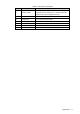
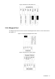
Table 1-2 Rear panel description
No.
Name
Description
1
Tamper switch
The VTO would make alarm sound if it is being
removed from the wall by force, and the alarm will
also be sent to the management center.
2
SD card slot
Reserved for future use.
3
Cable ports
See "2.2 Connecting Cable."
4
Ethernet port
Connects to the network with Ethernet cable.
5
Power port
Inputs 12V DC power.
6
USB port
Reserved for future use.
7
Screw hole
Put in screws to fix the VTO.