Model F VTO VTO6441F/VTO6421F Quick Start Guide V1.0.
Regulatory Information The regulatory information herein might vary according to the model you purchased. Some information is only applicable for the country or region where the product is sold. FCC Information Changes or modifications not expressly approved by the party responsible for compliance could void the user's authority to operate the equipment. FCC conditions: This device complies with part 15 of the FCC Rules.
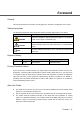
Foreword General This Guide introduces the structure, mounting process, and basic configuration of the device. Safety Instructions The following categorized signal words with defined meaning might appear in the Guide. Signal Words WARNING CAUTION Meaning Indicates a medium or low potential hazard which, if not avoided, could result in slight or moderate injury. Indicates a potential risk which, if not avoided, could result in property damage, data loss, lower performance, or unpredictable result.
All the designs and software are subject to change without prior written notice. The product updates might cause some differences between the actual product and the Guide. Please contact the customer service for the latest program and supplementary documentation. There still might be deviation in technical data, functions and operations description, or errors in print. If there is any doubt or dispute, please refer to our final explanation.
Important Safeguards and Warnings The following description is the correct application method of the device. Please read the manual carefully before use, in order to prevent danger and property loss. Strictly conform to the manual during application and keep it properly after reading. Operating Requirement Please don’t place and install the device in an area exposed to direct sunlight or near heat generating device. Please don’t install the device in a humid, dusty or fuliginous area.
Table of Contents Regulatory Information ............................................................................................................................ II Foreword .................................................................................................................................................. III Important Safeguards and Warnings ..................................................................................................... V 1 Appearance ................................
4.3 Project Mode ............................................................................................................................... 20 4.3.1 Entering Project Mode ...................................................................................................... 20 4.3.2 Modifying IP Address ........................................................................................................ 20 4.3.3 Adding Face Data ........................................................................
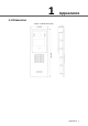
1 Appearance 1.
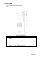
1.2 Front Panel For the description of the front panel, see Table 1-1. Face recognition is available on select models. Figure 1-2 Front panel Table 1-1 Front panel description No. Name Description 1 Fill light 2 Light sensor Detects ambient lighting condition. 3 Camera Monitors door area, and recognizes face information. 4 MIC Inputs audio. 5 Screen Displays information. 6 Access card reader Provides extra light when recognizing faces.
No. Name Description Press to operate the VTO. Number 0–9: Press to input numbers; 2/4/6/8 can act as up/down/left/right when selecting options. 7 : Press to delete the previous character, resume to the previous interface, or end the current call. : Press to go to the password input interface, or confirm. : Press to call a certain room after entering the room Dialing area number. / Outputs audio. 8 Speaker : Press to call the management center. : Press to select options. 1.
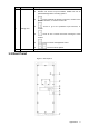
Table 1-2 Rear panel description No. Name Description 1 Tamper switch The VTO would make alarm sound if it is being removed from the wall by force, and the alarm will also be sent to the management center. 2 SD card slot Reserved for future use. 3 Cable ports See "2.2 Connecting Cable." 4 Ethernet port Connects to the network with Ethernet cable. 5 Power port Inputs 12V DC power. 6 USB port Reserved for future use. 7 Screw hole Put in screws to fix the VTO.
2 Installation 2.1 Installation Requirement 2.1.1 Notice Do not install the VTO to places with condensation, high temperature, grease or dust, chemical corrosion, direct sunlight, or zero shelter. The installation and adjustment must be finished by professional crew, and do not disassemble the VTO. 2.1.2 Guidance See Figure 2-1 for the reference of the installation position, and for the VTO horizontal viewing angle, see Table 2-1.
Figure 2-2 Electronic lock connection Figure 2-3 Magnetic lock connection Installation 6
Figure 2-4 Electro-mechanical lock connection 2.2.2 RS-485 Port This port can be used to connect to RS-485 devices. See Figure 2-5. Figure 2-5 RS-485 port 2.2.3 Alarm I/O and Power Port This port can be used to connect to 2 alarm-in devices and 2 alarm-out devices. See Figure 2-6.
Figure 2-6 Alarm I/O and power Port 2.2.4 Wiegand Port The Wiegand port can be used to connect to the Wiegand card reader or access control device. See Figure 2-7.
2.3 Installing VTO Figure 2-9 VTO installation Table 2-2 Item list Step 1 Step 2 Step 3 Step 4 Step 5 Step 6 No. Item No. Item 1 Wall 2 Mounting box 3 VTO 4 Screw Cut an opening with the size of the mounting box in the wall. Pull the reserved cables through the cable hole in the mounting box. Fix the mounting box in the wall with cement or screws. Connect the cables to the ports on the VTO rear panel. See "2.2 Connecting Cable." Fix the VTO in the mounting box with the screws.
3 Configuration This chapter introduces how to initialize, connect, and make primary configurations to the VTO and VTH devices to realize basic functions, including device management, calling, and monitoring. For more detailed configuration, see the user's Manual. 3.1 Configuration Process Before configuration, check every device and make sure there is no short circuit or open circuit in the circuits. Step 1 Plan IP address for every device, and also plan the unit number and room number you need.
Figure 3-1 Device initialization Step 3 Enter and confirm the password, and then click Next. The Email setting interface is displayed. Step 4 Select the Email check box, and then enter your Email address. This Email address can be used to reset the password, and it is recommended to finish this setting. Step 5 Click Next. The initialization succeeded. Step 6 Click OK. The login interface is displayed. See Figure 3-2. Figure 3-2 Login interface 3.3.
Figure 3-3 Main interface Step 2 Select Local Setting > Basic. The device properties are displayed. See Figure 3-4. Figure 3-4 Device properties Step 3 In the VTO No. input box, enter the VTO number you planned for this VTO, and then click Confirm to save. 3.3.3 Configuring Network Parameters Step 1 Select Network Setting > Basic. The TCP/IP information is displayed. See Figure 3-5. Figure 3-5 TCP/IP information Step 2 Enter the network parameters you planed, and then click Save.
3.3.4 Configuring SIP Server The SIP server is required in the network to transmit intercom protocol, and then all the VTO and VTH devices connected to the same SIP server can make video call between each other. You can use VTO device or other servers as SIP server. Step 1 Select Network Setting > SIP Server. The SIP Server interface is displayed. See Figure 3-6. Figure 3-6 SIP server Step 2 Select the server type you need.
Select the server type you need in the Server Type list, and then see the corresponding manual for the detailed configuration. 3.3.5 Adding VTO Devices You can add VTO devices to the SIP server, and all the VTO devices connected to the same SIP server can make video call between each other. This section applies to the condition in which a VTO device works as SIP server, and if you are using other servers as SIP server, see the corresponding manual for the detailed configuration.
Step 3 Configure the parameters, and be sure to add the SIP server itself too. See Table 3-2. Table 3-2 Add VTO configuration Parameter Description Rec No. The VTO number you configured for the target VTO. See the details in "3.3.2 Configuring VTO Number." Register Password Keep default value. Build No. Unit No. Available only when other servers work as SIP server. IP Address The IP address of the target VTO. Username The user name and password for the web interface of the target VTO.
Figure 3-10 Add single room number 2) Configure room information. See Table 3-3. Table 3-3 Room information Parameter Description First Name Last Name Enter the information you need to differentiate each room. Nick Name The room number you planned. Room No. If you use multiple VTH devices, the room number of the master VTH should be "room number#0", and the room number of the extension VTH should be "room number#1", "room number#2", and so on.
Figure 3-11 Add in batch All the added room numbers are displayed. Click Refresh to view the latest status, and click Clear to delete all the room numbers. 3.4 Verifying Configuration 3.4.1 Calling VTH from VTO Step 1 Dial room number on the VTO. Step 2 Press . The VTO is calling the VTH. See Figure 3-12. Figure 3-12 Call screen Step 3 Tap on the VTH to answer the call. 3.4.2 Doing Monitor from VTH Step 1 In the main interface of the VTH, select Monitor > Door. The Door interface is displayed.
Figure 3-13 Door Step 2 Select the VTO you need to do monitor. The monitor screen is displayed. See Figure 3-14.
4 Operating VTO 4.1 Call Function 4.1.1 Calling single VTH See "3.4.1 Calling VTH from VTO." 4.1.2 Calling Multiple VTH Devices If the VTO you are visiting works as SIP server, and there are multiple VTH devices being used, when you call the master VTH, all the extension VTH devices would also receive the call. Before calling, be sure to: Enable Group Call in Local Setting > Basic. See the VTO user's manual. Add master VTH and the extension VTH. See "3.3.6 Adding Room Number." 4.1.
4.2.4 Unlock From VTH You can tap the unlock button on VTH to unlock the door when VTO and VTH are having phone call or you are doing monitor. 4.2.5 Unlock From the Management Center You can unlock the door from the management center when VTO is calling the management center, VTO and the management center are having phone call, or you are doing monitor from the management center. 4.
You can add 50 faces at most under one room number. Step 2 Select Face Registration. The VTO starts recognizing and adding face data. Press Step 3 After the registration is finished, press exit. to restart. to confirm, and then press to 4.3.4 Issuing Card Step 1 In the project mode, select User Registration. The Input room number interface is displayed. Step 2 Enter the number of the room to which you need to issue access card, and then press .
Appendix 1 Cybersecurity Recommendations Cybersecurity is more than just a buzzword: it’s something that pertains to every device that is connected to the internet. IP video surveillance is not immune to cyber risks, but taking basic steps toward protecting and strengthening networks and networked appliances will make them less susceptible to attacks. Below are some tips and recommendations on how to create a more secured security system.
5. 6. 7. 8. 9. 10. 11. 12. 13. 14. Change Default HTTP and Other Service Ports We suggest you to change default HTTP and other service ports into any set of numbers between 1024~65535, reducing the risk of outsiders being able to guess which ports you are using. Enable HTTPS We suggest you to enable HTTPS, so that you visit Web service through a secure communication channel.
The network should be partitioned and isolated according to the actual network needs. If there are no communication requirements between two sub networks, it is suggested to use VLAN, network GAP and other technologies to partition the network, so as to achieve the network isolation effect. Establish the 802.1x access authentication system to reduce the risk of unauthorized access to private networks.
Appendix 2 Packing List Packing List Open the package and check whether all the components are included.