Villa Door Station (Version 4.3) (VTO) Baseline Quick Start Guide V1.0.
Foreword General This manual introduces the structure, mounting process, and basic configuration of the door station (VTO). Safety Instructions The following categorized signal words with defined meaning might appear in the manual. Signal Words WARNING CAUTION Meaning Indicates a medium or low potential hazard which, if not avoided, could result in slight or moderate injury.
⚫ If there is any uncertainty or controversy, please refer to our final explanation.
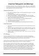
Important Safeguards and Warnings The following description is the correct application method of the device. Please read the manual carefully before use to prevent danger and property loss. Strictly conform to the manual during application and keep it properly after reading. Operating Requirement ⚫ ⚫ ⚫ ⚫ ⚫ ⚫ ⚫ ⚫ Do not place and install the device in an area exposed to direct sunlight or near heat generating devices. Do not install the device in a humid, dusty or fuliginous area.
equipment off and on, the user is encouraged to try to correct the interference by one or more of the following measures: —Reorient or relocate the receiving antenna. —Increase the separation between the equipment and receiver. —Connect the equipment into an outlet on a circuit different from that to which the receiver is connected. —Consult the dealer or an experienced radio/TV technician for help.
Table of Contents Foreword .................................................................................................................................................... I Important Safeguards and Warnings .................................................................................................... III 1 Network Diagram ................................................................................................................................... 1 2 Appearance ..............................
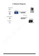
1 Network Diagram 1
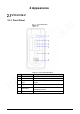
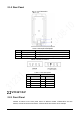
2 Appearance VTO2101E-P 2.1.1 Front Panel VTO2101E-P Table 2-1 Front panel description No. Name Description 1 MIC Inputs audio. 2 Camera Monitors doorway area. 3 IR illunimation light Provides extra IR light for the camera when it is dark. 4 Light sensor Detects ambient lighting condition. 5 Call button Press the button to call VTH or the management center. 6 Speaker Outputs audio.
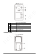
2.1.2 Rear Panel VTO2101E-P Table 2-2 Rear panel description No. Name Description 1 Network port Connected to the network with network cables. 2 RS-485 ports See Figure 2-3 and Table 2-3. 3 Cable tray You can thread cables through the cable tray. Cable connection Table 2-3 Port description DOOR POWER/485 No. Name No. Name 1 NO 1 +12V 2 NC 2 GND 3 COM 3 RS-485A 4 ALARM IN 4 RS-485B VTO3211D-P 2.2.1 Front Panel Number of buttons on the front panel varies on different models.
VTO3211D-P Table 2-4 Front panel description No. Name Description 1 IR illumination light Provides extra IR light for the camera when it is dark. 2 Camera Monitors doorway area. 3 Speaker Outputs audio. 4 Call button Press the button to call VTH or the management center. 5 MIC Inputs audio. 2.2.
Table 2-5 Rear panel description No. Name Description 1 Cable ports See Figure 2-6 and Table 2-6. 2 Cable tray You can thread the cable through the cable tray. Cable connection Table 2-6 Cable port description No. Name No.
VTO2211G/VTO1201G 2.3.1 Front Panel Front panel of VTO2211G/VTO1201G Table 2-7 Front panel description Name Description 1 Camera 2 Press the button to call indoor monitor (VTH) or the management center. 3 Indicator light. Off: The device in standby mode; Solid green: door station (VTO) making a call; Solid blue: door station (VTO) during a call; Yellowish green: When you unlock the door through VTH while door station (VTO) is making a call.
2.3.2 Rear Panel Rear panel of VTO2211G/VTO1201G Table 2-8 Rear panel description No. Description No.
Table 2-9 Port description No. Name No. Name 1 Alarm input device 14 DOOR1_NC 2 Alarm output device 15 Not available 3 DC_IN- 16 DOOR1_COM 4 DC_IN+ 17 Not available 5 ALARM_IN 18 DOOR1_NO 6 +12V_OUT 19 Not available 7 GND 20 GND 8 GND 21 Not available 9 ALARM_NO 22 DOOR1_FB 10 RS485B 23 Not available 11 ALARM_COM 24 GND 12 RS485A 25 Not available 13 Not available 26 DOOR1_PUSH VTO1201G cable connection Table 2-10 Port description No. Name No.
Connecting lock cables Table 2-11 Port description No. Name No.
3 Installation Notice ⚫ ⚫ Do not install the door station (VTO) at places with condensation, high temperature, grease or dust, chemical corrosion, direct sunlight, or zero shelter. The installation and adjustment must be finished by professionals, and do not disassemble the VTO. Guidance See Figure 3-1 the installation position. The door station (VTO) horizontal angle of view varies with different models, face the center of the door station (VTO) as much as possible.
4 Configuration This chapter introduces how to initialize, connect, and make primary configurations to door stations (VTO) and indoor monitors (VTH) to realize basic functions, including device management, calling, and monitoring. For details, see the user manual. Configuration Process Before configuration, check each device and make sure there is no short circuit or open circuit. Plan IP address for each device, and also plan the apartment number and room number you need. Configure door stations (VTO).
Open the internet browser on the PC, then enter the default IP address of the door station (VTO) in the address bar, and then press Enter. Device initialization Enter and confirm the password, and then click Next. The email setting interface is displayed. Select the Email check box, and then enter your Email address. This Email address can be used to reset the password, and it is recommended to finish this setting. Click Next. The initialization succeeded. Click OK. Login interface 4.3.
Log in to the web interface of the door station (VTO), and then the main interface is displayed. Main interface Select Local Setting > Basic. Device properties In the No. input box, enter the door station (VTO) number you planned for the door station (VTO) you are operating, and then click Confirm to save. 4.3.3 Configuring Network Parameters Select Network Setting > Basic. TCP/IP information Enter the network parameters you planed, and then click Save.
The door station (VTO) will restart, and you need to modify the IP address of your PC to the same network segment as the door station (VTO) to log in again. 4.3.4 Configuring SIP Server The SIP server is required in the network to transmit intercom protocol, and then all the door station (VTO) and indoor monitor (VTH) connected to the same SIP server can make video calls among each other. You can use door stations (VTO) or other servers as SIP server. Select Network Setting > SIP Server.
Parameter Description SIP Server Username The user name and password for the web interface of the SIP server. SIP Server Password ⚫ If other servers work as SIP server Select Express/DSS in the Server Type list, and then see the corresponding manual for the detailed configuration. 4.3.5 Configuring Call No. and Group Call You need to configure call No. on each door station (VTO), and then all the door stations (VTO) can call the defined room when you press the call button.
VTO No. management Click Add. Add door stations (VTO) Configure the parameters, and be sure to add the SIP server itself too. See Table 4-2. Table 4-2 Add door stations (VTO) Parameter Description Rec No. The door station (VTO) number you configured for the target door station (VTO). See the details in "4.3.2 Configuring Door Station (VTO) Number." Register Password Keep default value. Build No. Unit No. Available only when other servers work as SIP server.
Click Save. 4.3.7 Adding Room Number You can add the planned room number to the SIP server, and then configure the room number on indoor monitors (VTH) to connect them to the network. This section applies to the condition in which a door station (VTO) works as SIP server, and if you use other servers as SIP server, see the corresponding manual for the detailed configuration. The room number can contain 6 digits of numbers or letters or their combination at most, and the room number must be unique.
Add single room number Configure room information. See Table 4-3. Table 4-3 Room information Parameter Description First Name Last Name Enter the information you need to differentiate each room. Nick Name The room number you planned. ⚫ Room No. ⚫ If you use multiple indoor monitors (VTH), the room number of the master indoor monitor (VTH) should be "room number#0", and the room number of the extension VTH should be "room number#1", "room number#2", and so on.
Verifying Configuration 4.4.1 Calling VTH from VTO Press the call button on the door station (VTO) to start a call with the indoor monitor (VTH). Call screen Tap on the VTH to answer the call. 4.4.2 Watching Monitoring Videos on the VTH In the main interface of the VTH, select Monitor > Door. Door Select a door station (VTO) to watch monitoring videos.
Watching monitoring videos 20
5 App Installation and Adding Device Scan the following QR code to download and install the app. Before adding the door station (VTO) to the gDMSS Plus, you need to change IP address of the door station (VTO), make sure that the door station (VTO) and the router are connected to the same network, and connect the door station (VTO) to the power source. On your mobile phone, tap , and then follow the onscreen instructions until the region selection interface is displayed. Select a region.
Home Tap on the Home interface. The Device Manager interface is displayed. Tap on the upper right corner of the Device Manager interface.
5.1.2 Add through Wired Network Tap IP/Domain on Figure 5-3. The Add Device interface is displayed. Add device Tap VTO on the Add Device interface. The Add Device interface is displayed. Add device Enter Address (IP address of the door station (VTO)), Device Name, and Device Password. Tap .
The door station (VTO) is added. You can watch videos captured by the door station (VTO), call the door station (VTO), unlock doors when there is call from the door station (VTO), and more. Door 5.1.3 Add through Soft Access Point (AP) Connect the door station to the power source. Go to the WLAN interface of your mobile phone. Press and hold the call button on the door station for over 5 seconds until you hear a beep. Connect your phone to the VTO2211G-WP_b67356.. network.
Mobile phone WLAN Tap on the upper right corner of the Device Manager interface (see Figure 5-3). Tap SN/Scan on Figure 5-3.
Scan the QR code Scan the QR code at the rear cover of the door station. The QR code can also be found in Network > Basic > P2P on the web interface, Tap Next.
Add device Tap on the upper right corner.
Select network configuration mode Select Switch to AP Configuration. Tap Next. Set phone network Tap Set.
Select a Wi-Fi Tap a Wi-Fi name. Enter Wi-Fi password Enter the Wi-Fi password. Tap Next.
Add device Enter device name and device password (door station web login password). Tap . The door station (VTO) is added. You can watch videos captured by the door station (VTO), call the door station (VTO), unlock doors when there is call from the door station (VTO), and more. After adding door stations to the App, you need to subscribe messages, and then push notifications can be sent to your phone.
Door 31
Cybersecurity Recommendations Cybersecurity is more than just a buzzword: it’s something that pertains to every device that is connected to the internet. IP video surveillance is not immune to cyber risks, but taking basic steps toward protecting and strengthening networks and networked appliances will make them less susceptible to attacks. Below are some tips and recommendations on how to create a more secured security system. Mandatory actions to be taken for basic equipment network security: 1.
6. 7. 8. 9. 10. 11. 12. 13. 14. We suggest you to change default HTTP and other service ports into any set of numbers between 1024~65535, reducing the risk of outsiders being able to guess which ports you are using. Enable HTTPS We suggest you to enable HTTPS, so that you visit Web service through a secure communication channel. Enable Whitelist We suggest you to enable whitelist function to prevent everyone, except those with specified IP addresses, from accessing the system.
⚫ suggested to use VLAN, network GAP and other technologies to partition the network, so as to achieve the network isolation effect. Establish the 802.1x access authentication system to reduce the risk of unauthorized access to private networks.