IP Indoor Monitor (Version 4.2) Quick Start Guide V1.0.
Foreword General This document mainly introduces structure, installation process, commissioning, and verification process of indoor monitors (VTH). Safety Instructions The following categorized signal words with defined meaning might appear in the manual. Signal Words Meaning CAUTION Indicates a potential risk which, if not avoided, could result in property damage, data loss, lower performance, or unpredictable result. Provides methods to help you solve a problem or save you time.
⚫ ⚫ Please visit our website, contact the supplier or customer service if there is any problem occurred when using the device. If there is any uncertainty or controversy, please refer to our final explanation. Regulatory Information European Directives Compliance This product complies with the applicable CE marking directives and standards: ⚫ Low Voltage (LVD) Directive 2014/35/EU. ⚫ Electromagnetic Compatibility (EMC) Directive 2014/30/EU.
equipment off and on, the user is encouraged to try to correct the interference by one or more of the following measures: ⚫ Reorient or relocate the receiving antenna. ⚫ Increase the separation between the equipment and receiver. ⚫ Connect the equipment into an outlet on a circuit different from that to which the receiver is connected. ⚫ Consult the dealer or an experienced radio/TV technician for help.
Important Safeguards and Warnings The following description is the correct application method of the device. Please read the Guide carefully before use to prevent danger and property loss. Strictly conform to the Guide during application and keep it properly after reading. Operating Requirement ⚫ ⚫ ⚫ ⚫ ⚫ ⚫ ⚫ ⚫ Do not place and install the device in an area exposed to direct sunlight or near heat generating device. Do not install the device in a humid, dusty or fuliginous area.
Table of Contents Foreword .................................................................................................................................................. I Important Safeguards and Warnings .................................................................................................. IV 1 Rear Panel Port ...................................................................................................................................... 1 VTH5421E-H ..................................
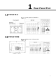
1 Rear Panel Port VTH5421E-H Rear panel of VTH5421E-H VTH5421CHM Rear panel of VTH5421CHM 1
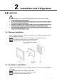
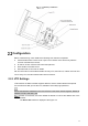
2 Installation and Cofiguration Installation ⚫ ⚫ ⚫ ⚫ Do not install VTH in harsh environment with condensation, high temperature, dust, corrosive substance and direct sunlight. In case of abnormality after power on, unplug network cable and cut off power supply at once. Power on after troubleshooting. Engineering installation and debugging shall be done by professional teams. Do not dismantle or repair arbitrarily in case of device failure. Contact after-sales service.
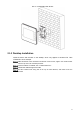
Installation with 86 box 2.1.3 Desktop Installation Install the device with bracket on the desktop, which only applies to handset VTH. Take VTH5221E-H as an example. With two M3×6 cross recessed countersunk head screws, tighten the metal bracket onto the top two nuts of desktop bracket. Connect cables. For details, see "1 Rear Panel Port." Thread the cable through wire outlet. Put the handset VTH along slot at the top of metal bracket, and install it into the bracket.
Desktop installation Configuration Before commissioning, check whether the following work has been completed. ⚫ Check whether there is short circuit or open circuit. Power on the device only after the circuit is confirmed to be normal. ⚫ IP and No. of each VTO and VTH have been planned. ⚫ Know location of the SIP server. ⚫ Scan QR code on the cover for details.
Device initialization Enter password and confirm password, and then click Next. Select Email, and then enter your email address. This email address is used to reset the password Enter default address in the browser to log in to the web interface. Default username is admin. Password is the new one set during initialization. Select Network Setting > Basic. The TCP/IP interface is displayed, see Figure 2-5. TCP/IP Enter the planned IP address, subnet mask and gateway, and then click OK.
Device properties 1) 2) Select TCP/IP from the System Type drop-down list. Click OK to save the settings. Restart the device manually, or wait for the device to restart automatically, and then the settings can be valid. Log in to the web interface again, and then select Network Setting > SIP Server. The SIP Server interface is displayed, see Figure 2-7. SIP server (1) 1) 2) Select server type. When this VTO or another VTO works as SIP server, select VTO from the Server Type drop-down list.
SIP server (2) ⚫ ⚫ This VTO works as SIP server. Select SIP Server Enable, and click OK to save the configuration. The VTO will restart automatically. Another VTO or platform works as SIP server. Set parameters according to Table 2-1 and click OK. The VTO will restart automatically. Table 2-1 SIP server parameter Parameter Description IP Address IP address of SIP server. It is 5060 by default when another VTO works as SIP server. It is 5080 by default when the platform works as SIP server.
VTO No. management Click Add, set outdoor station parameters according to Table 2-2 and click OK. Repeat this step to add other outdoor stations in the group. Table 2-2 VTO No. management description Parameter Description VTO No. VTO number. Register Password Signaling interactive use in SIP system. Use default value. Build No. Number of the building where VTO is located. Unit No. Number of the unit where VTO is located. IP Address IP address of VTO.
Parameter Description ⚫ ⚫ Register Type Modify VTH room number consists of 1–6 numbers, letters, or their combinations. It shall be consistent with room number configured at VTH. When there are master VTH and extensions, to realize group call function, master VTH short no. shall end with “#0”, whereas extension VTH short no. shall end with #1, #2 and #3. For example, if master VTH is 101#0, extensions will be 101#1, 101#2… Signaling interactive use in SIP system. Keep the default value. 2.2.
IP addresses of VTH and VTO shall be in the same network segment. Otherwise, VTH will fail to obtain VTO information after configuration. WLAN LAN ⚫ LAN Enter local IP, subnet mask, and gateway, and then tap OK. Or tap to enable DHCP function and obtain IP info automatically. If the device has WLAN function, tap WLAN to set it. ⚫ WLAN 1) Tap to enable Wi-Fi function. Available Wi-Fi list will be displayed, see Figure 2-14.
Wi-Fi list 2) Connect Wi-Fi. The system has 2 access ways. ◇ On WLAN interface, select Wi-Fi, tap Wireless IP to enter local IP, subnet mask, and gateway, and then tap OK. ◇ At WLAN interface, select Wi-Fi, tap Wireless IP, tap to enable DHCP function and obtain IP info automatically. To obtain IP info with DHCP function, use a router with DHCP function. Tap VTH Config. The VTH Config interface is displayed, see Figure 2-15. VTH configuration ⚫ Be used as a master VTH.
Enter Room No. (such as 9901 or 101#0) and tap OK to save. ⚫ ⚫ ⚫ 1) 2) Room No. shall be the same with VTH Short No., which is set when adding VTH at web interface. Otherwise, it will fail to connect VTO. If there is extension VTH, room No. shall end with #0. Otherwise, it will fail to connect VTO. Be used as an extension VTH. Tap Master and the icon switches to Extension. Enter room No. (such as 101#1) and master IP (IP address of master VTH).
Parameter Description Domain Registration domain of SIP server, which can be null. When VTO works as SIP server, registration domain of SIP server shall be VDP. User Name Login Pwd 2) User name and password to log in to SIP server. Set Enable Status to be . 3) Tap OK to save settings. Tap VTO Config. The VTO Config interface is displayed, see Figure 2-17. VTO configuration Add VTO or fence station. ⚫ Add main VTO. 1) Enter main VTO name, VTO IP address, user name and password.
Debugging 2.3.1 VTO Calls VTH Dial VTH room No. (such as 101) at VTO to call VTH. VTH pops up monitoring image and operating icon, see Figure 2-18. The following figure means that SD card has been inserted into VTH. If SD card is not inserted, recording and snapshot icons are gray. Call VTH from VTO 2.3.2 VTH Monitors VTO VTH is able to monitor VTO, fence station or IPC. Take VTO for example. Select Monitor > Door, see Figure 2-19. Select the VTO to enter monitoring image, see Figure 2-20.
Door Monitoring image 15
Cybersecurity Recommendations Cybersecurity is more than just a buzzword: it’s something that pertains to every device that is connected to the internet. IP video surveillance is not immune to cyber risks, but taking basic steps toward protecting and strengthening networks and networked appliances will make them less susceptible to attacks. Below are some tips and recommendations on how to create a more secured security system. Mandatory actions to be taken for basic equipment network security: 1.
5. 6. 7. 8. 9. 10. 11. 12. 13. 14. Change Default HTTP and Other Service Ports We suggest you to change default HTTP and other service ports into any set of numbers between 1024~65535, reducing the risk of outsiders being able to guess which ports you are using. Enable HTTPS We suggest you to enable HTTPS, so that you visit Web service through a secure communication channel.
⚫ ⚫ The network should be partitioned and isolated according to the actual network needs. If there are no communication requirements between two sub networks, it is suggested to use VLAN, network GAP and other technologies to partition the network, so as to achieve the network isolation effect. Establish the 802.1x access authentication system to reduce the risk of unauthorized access to private networks.