Digital VTH (Version 4.2) Quick Start Guide V1.1.
Cybersecurity Recommendations Mandatory actions to be taken towards cybersecurity 1. Change Passwords and Use Strong Passwords: The number one reason systems get “hacked” is due to having weak or default passwords. It is recommended to change default passwords immediately and choose a strong password whenever possible. A strong password should be made up of at least 6 numbers. 2.
Foreword General This document mainly introduces structure, installation process, debugging and verification process of digital VTH products. Device Upgrade Please don’t cut off power supply during device upgrade. Power supply can be cut off only after the device has completed upgrade and has rebooted. Safety Instructions The following categorized signal words with defined meaning might appear in the Manual.
⚫ ⚫ ⚫ ⚫ ⚫ ⚫ ⚫ ⚫ All the designs and software are subject to change without prior written notice. The product updates might cause some differences between the actual product and the Guide. Please contact the customer service for the latest program and supplementary documentation. There still might be deviation in technical data, functions and operations description, or errors in print. If there is any doubt or dispute, please refer to our final explanation.
Important Safeguards and Warnings The following description is the correct application method of the device. Please read the Guide carefully before use, in order to prevent danger and property loss. Strictly conform to the Guide during application and keep it properly after reading. Operating Requirement ⚫ ⚫ ⚫ ⚫ ⚫ ⚫ ⚫ ⚫ Please don’t place and install the device in an area exposed to direct sunlight or near heat generating device. Please don’t install the device in a humid, dusty or fuliginous area.
Table of Contents Cybersecurity Recommendations ........................................................................................................I Foreword ...............................................................................................................................................II Important Safeguards and Warnings ................................................................................................ IV 1 Product Structure .................................................
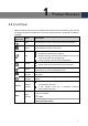
1 Product Structure 1.1 Front Panel Different models of devices may have different front panel dimensions and key types, but keys or indicators with the same silkscreen or icon have the same function. Please refer to Table 1-1 for details. Icon or Silkscreen Network DND Name Description SOS Press this key to call the Call Center in case of emergency. Menu Press this key to return to main menu. Call In case of incoming call, press this key to answer the call.
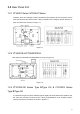
1.2 Rear Panel Port 1.2.1 VTH5221 Series /VTH5241 Series VTH5221 series and VTH5241 series have different port positions at the rear panel, but the same port provides the same function. Taking VTH5221 as an example, specific functions of ports are introduced, as shown in Figure 1-1. Figure 1-1 1.2.2 VTH5221E-H/VTH5221EW-H Rear panel of VTH5221E-H/VTH5221EW-H is shown in Figure 1-2. Figure 1-2 1.2.
In VTH15XX-S2 type B series, different types of digital VTH have different port positions, but the same port provides the same function. Taking VTH1560B-S2 as an example, specific functions of ports are introduced, as shown in Figure 1-4. In VTH15XX type CH series, different types of digital VTH have different port positions, but the same port provides the same function. Taking VTH1550CH as an example, specific functions of ports are introduced, as shown in Figure 1-5.
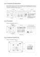
1.2.4 VTH5222CH/VTH5222CHW-2 Except different numbers of 2-wire port, VTH5222CH and VTH5222CHW-2 are the same in other aspects. VTH5222CH has 1 group of 2-wire port, while VTH1550CHW-2 has 3 groups of 2-wire port. VTH5222CH is shown in Figure 1-7. Figure 1-7 1.2.5 VTH1660CH Its ports are described in Figure 1-8. Figure 1-8 1.2.6 VTH2221A/VTH2221A-S2 Its ports are described in Figure 1-9.
Figure 1-9 1.2.7 VTH2421FB/VTH2421FS Its ports are described in Figure 1-9.
2 Installation and Debugging 2.1 Installation ⚫ ⚫ ⚫ ⚫ Don’t install VTH in bad environment, such as condensation, high temperature, stained, dusty, chemically corrosive and direct sunshine environment. In case of abnormality after power on, please pull out network cable and cut off power supply at once. Power on after troubleshooting. Engineering installation and debugging shall be done by professional teams. Please don’t dismantle or repair arbitrarily in case of device failure.
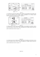
2.1.2 Installation with 86 Box Install the device with 86 box, which is suitable for all types of devices. Take “VTH1560B/BW” for example. Embed 86 box into a wall at a proper height. Fix installation bracket onto 86 box with screws. Put the device into installation bracket from top down. Figure 2-2 2.1.3 Desktop Installation with Bracket Install the device with bracket on the desktop, which only applies to handset VTH. Take “VTH5221E-H” for example.
Figure 2-3 2.2 Debugging Carry out debugging to ensure that the device can realize basic network access, call and monitoring functions after installation. Before debugging, please check whether the following work has been completed. ⚫ Check whether there is short circuit or open circuit. Power on the device only after the circuit is confirmed to be normal. ⚫ IP and no. of every VTO and VTH have been planned. ⚫ Ensure deployment position of SIP server. ⚫ Please scan QR code on the cover for details.
Figure 2-4 According to interface prompt, enter “Password” and “Confirm Password”, and click “Next”. Select “Email” and enter your Email address. This Email address is used to reset the password, so it is recommended that it should be set. Enter default address in the browser to login WEB interface. Default username is admin. Password is the new one set during initialization. Select “Network Setting > Basic”. The system displays “TCP/IP” interface, as shown in Figure 2-5.
Figure 2-6 Select system type as “TCP/IP”. Click “OK” to save the settings. Reboot the device manually, or wait for auto reboot and put the settings into effect. Login WEB interface again; select “Network Setting > SIP Server”. The system displays “SIP Server” interface, as shown in Figure 2-7. Figure 2-7 Select server type. When this VTO or another VTO works as SIP server, select “Server Type” to be “VTO”. It applies to a scenario where there is only one unit.
Figure 2-8 ⚫ ⚫ This VTO works as SIP server. Select “SIP Server Enable”, and click “OK” to save config. The VTO reboots automatically. Another VTO or platform works as SIP server. Set parameters by reference to Table 2-1 and click “OK”. The VTO reboots automatically. Parameter Description IP Address IP address of SIP server. Port Username/Password SIP Domain Login Username/ Password It is 5060 by default when another VTO works as SIP server.
Figure 2-9 Click “Add”, set outdoor station parameters by reference to Table 2-2 and click “OK”. Repeat this step to add other outdoor stations in the group. Parameter Description VTO No. VTO number. Register Password Signaling interactive use in SIP system. Adopt default value. Build No. Number of the building where VTO is located. Unit No. Number of the unit where VTO is located. IP Address IP address of VTO. Username/Password Username and password to login WEB interface of this VTO.
Parameter Description Set VTH room number. ⚫ Room No. ⚫ VTH room number consists of 1~6 numbers, letters, or their combinations. It shall be consistent with room number configured at VTH. When there are master VTH and extensions, to realize group call function, master VTH short no. shall end with “#0”, whereas extension VTH short no. shall end with #1, #2 and #3. For example, if master VTH is 101#0, extensions will be 101#1, 101#2… Register Type Signaling interactive use in SIP system.
Figure 2-11 Enter “Password”, “Confirm Pwd” and “Email”. Press [OK]. Press [Setting] for more than 6 seconds, enter the password set during initialization, and click [OK]. Click [Network]. The system displays “Network” interface, as shown in Figure 2-12 or Figure 2-13. IP addresses of VTH and VTO shall be in the same network segment. Otherwise, VTH will fail to obtain VTO info after configuration.
Enter “Local IP”, “Subnet Mask” and “Gateway”, press [OK]. Or press to enable DHCP function and obtain IP info automatically. If the device has WLAN function, please click “WLAN” tab to set it. ⚫ WLAN Press to enable Wi-Fi function. The system displays available Wi-Fi list, as shown in Figure 2-14. Figure 2-14 Connect Wi-Fi. The system has 2 access ways as follows. ◇ At “WLAN” interface, select Wi-Fi, click “Wireless IP” tab to enter “Local IP”, “Subnet Mask” and “Gateway”, and press [OK].
Figure 2-15 Be used as a master VTH. Enter “Room No.” (such as 9901 or 101#0) and press “OK” to save. ⚫ “Room no.” shall be the same with “VTH Short No.”, which is set when adding VTH at WEB interface. Otherwise, it will fail to connect VTO. ⚫ In case of extension VTH, room no. shall end with #0. Otherwise, it will fail to connect VTO. ⚫ Be used as an extension VTH. Press [Master] and switch to “Extension”. Enter “Room No.” (such as 101#1) and “Master IP” (IP address of master VTH).
Figure 2-16 Set parameters of SIP server by reference to Table 2-4. Parameter Description Server IP When the platform works as SIP server, server IP is IP address of the platform. When VTO works as SIP server, server IP is IP address of the VTO. Network Port When the platform works as SIP server, network port is 5080. When VTO works as SIP server, network port is 5060. User Name Register Pwd Registration domain of SIP server, which can be null.
Figure 2-17 Add VTO or fence station. ⚫ Add main VTO. Enter “Main VTO Name”, “VTO IP Address”, “User Name” and “Password”. Switch the “Enable Status” to be ⚫ . “User Name” and “Password” shall be consistent with WEB login user name and password of VTO. Otherwise, it will fail to connect. Add sub VTO or fence station. Enter “Sub VTO/Fence Station Name”, “Sub VTO/Fence Station IP address”, “User Name” and “Password”. Switch the “Enable Status” to be Press / .
Figure 2-18 2.3.2 VTH Monitors VTO VTH is able to monitor VTO, fence station or IPC. Take “VTO” for example. Select “Monitor > Door”, as shown in Figure 2-19. Select the VTO to enter monitoring image, as shown in Figure 2-20. The following figure means that SD card has been inserted into VTH. If SD card is not inserted, recording and snapshot icons are gray.
Figure 2-19 Figure 2-20 20