
User's Manual

14
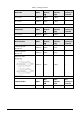
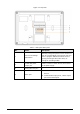
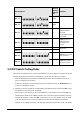
DIP Switch No.
Corresp
onding
Address
No.
Function
DIP 11
1024
DIP 12
2048
DIP 13
—
ON: Connect to
HDCVI camera
through
unshielded twisted
pair (UTP).
DIP 13
OFF: Connect to
HDCVI camera
through coax
cable.
DIP 14
—
—
Reserved.
DIP 15
—
—
DIP 16
—
ON: Set the VTH as
the extension.
DIP 16
—
OFF: Set the VTH
as the main VTH.
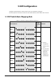
5.2 DIP Switch Coding Rules
This section introduces how to configure the address of a VTH through the coding rules of DIP
switches. By setting the switches in combination, you can get any value from 1-4094.
1. Find the mapping relation between the DIP switch number and the address number you
plan to configure from the table.
It follows a calculation rule that combing only the numbers listed in the Address No. only
to form a new address number.
2. Manually move the actuator(s) corresponding to the DIP switch(s) to the status ON, so that
the address of the VTH can be configured.
For example, if you want to set your VTH address as 4, you need to first find the mapping
relation (DIP 3 equals to the address number of 4) in the table, and the manually move the
actuator of the DIP 3 to the status ON. If you want to set your VTH address as 3, you need
to do the calculation (1+2=3; which equals to the value of DIP1 and DIP 2 combined
together in the mapping relation), and manually move both the actuator of DIP 1 and DIP 2