
User's Manual

10
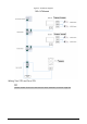
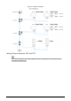
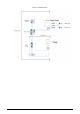
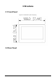
Figure 3-2 real panel
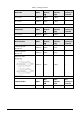
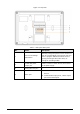
Table 3-1 Rear panel description
No.
Name
Description
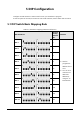
1
Dual In-line Package
(DIP) Switch
Manually change the position of the actuator to
that are corresponding to the function that you
want to program. DIP switches allow users to
quickly preconfigure the VTH a variety of
settings or operating modes.
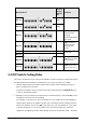
2
RS-485 and power
output port
Used to connect to other devices; and connect
to the power supply.
3
Analog two-wire port
—
4
Alarm port
●
Used connect to the alarm input and output
devices.
●
Include 6 alarm input ports, 1 alarm output
port and 2 camera ports.