2-wire Indoor Monitor User's Manual V1.0.
Foreword General This manual introduces the installation, functions and operations of the analog indoor monitor device (hereinafter referred to as "the VTH"). Read carefully before using the device, and keep the manual safe for future reference. Safety Instructions The following signal words might appear in the manual. Signal Words Meaning Indicates a high potential hazard which, if not avoided, will result in death or serious injury.
operations and technical data. If there is any doubt or dispute, we reserve the right of final explanation. ● Upgrade the reader software or try other mainstream reader software if the manual (in PDF format) cannot be opened. ● All trademarks, registered trademarks and company names in the manual are properties of their respective owners. ● Please visit our website, contact the supplier or customer service if any problems occur while using the device.
Important Safeguards and Warnings This section introduces content covering the proper handling of the device, hazard prevention, and prevention of property damage. Read carefully before using the device, and comply with the guidelines when using it. Operation Requirements ● Check whether the power supply is correct before use. ● Do not unplug the power cord on the side of the device while the adapter is powered on. ● Operate the device within the rated range of power input and output.
Table of Contents Foreword ............................................................................................................................................................................................ I Important Safeguards and Warnings ................................................................................................................................ III 1 Production Overview .........................................................................................................
.5.4 General Setting ...................................................................................................................................................31 6.5.4.1 Time and DND...........................................................................................................................................31 6.5.4.2 Display ..........................................................................................................................................................33 6.5.
1 Production Overview 1.1 Introduction The 2-wire analog indoor station (VTH) uses a 7-inch touch screen and uses the 2-wire system for communication. It supports preview of VTO and HDCVI cameras; supports intercom between VTO and VTH; and also remote unlocking, as well as connection to DMSS App. 1.2 Function Analog Communication Supports 2-wire communication. Video/Voice Call Make video or voice call to other VTOs. Monitoring Monitor VTO and HDCVI cameras.
Message View messages, including videos, pictures. Wi-Fi Networking Connect to Wi-Fi networks.
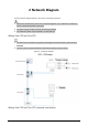
2 Network Diagram See the network diagram below to see all the networking scenarios. ● When there are 6 devices (VTH+VTO) connected together, only a maximum of 2 devices can be connected to power output port. ● The power supply of HDCVI camera cannot be grounded. ● The maximum power output allowed is 12 VDC/200 mA. Wiring One VTO and One VTH ● The two wires connected to the positive and negative terminals of OUT cannot be shortcircuited.
Figure 2-2 Network diagram Wiring One VTO and Two VTH (parallel connection) 4
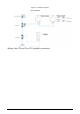
Figure 2-3 Network diagram Wiring Two VTO and Four VTH The DIP number of each VTO cannot be the same. Otherwise, connection might fail.
Figure 2-4 Network diagram Wiring Distance Between VTH and VTO It is recommended that the distance between the line termination terminal and the 2-wire controller not exceed 3 m.
Figure 2-5 Max distance 7
Table 2-1 Wiring Distance RVV Cable AWG Max. Distance (A) Max. Distance (B) Max. Quantity of Terminals 2* 0.5 mm² AWG 20 180 m 100 m 6 2* 1.5 mm² AWG 15 180 m 100 m 6 RVVP Cable AWG Max. Distance (A) Max. Distance (B) Max. Quantity of Terminals 2* 0.5 mm² AWG 20 150 m 100 m 6 AWG Max. Distance (A) Max. Distance (B) Max. Quantity of Terminals AWG 24 100 m 35 m 6 AWG 24 100 m 50 m 4 AWG 24 200 m 100 m 6 Telephone Wire AWG Max. Distance (A) Max. Distance (B) Max.
3 Structure 3.1 Front Panel Figure 3-1 Dimensions (unit: mm [inch]) 3.
Figure 3-2 real panel Table 3-1 Rear panel description No. Name Description 1 Dual In-line Package (DIP) Switch Manually change the position of the actuator to that are corresponding to the function that you want to program. DIP switches allow users to quickly preconfigure the VTH a variety of settings or operating modes. 2 RS-485 and power output port Used to connect to other devices; and connect to the power supply.
Figure 3-3 Alarm port Figure 3-4 RS-485 and power output port 11
4 Installation and Wiring ● The alarm input port is connected as dry contact. ● Do not install devices in harsh environment with condensation, high temperature, dust, corrosive substance and direct sunlight. ● In case of abnormality after powering on the device, cut off the power supply at once, and unplug the network cable. Power on after troubleshooting. ● Installation should be done by professional teams. Do not dismantle or repair the device by yourself in case of device failure.
5 DIP Configuration Configure the DIP switches to achieve the function you would like to program. At the rear panel of the VTH, there are two sets of DIP switches, each of which has a 8-switch. 5.1 DIP Switch Basic Mapping Rule Table 5-1 DIP Switch mapping relations and function DIP Switch No. Corresp onding Address No. DIP 1 1 DIP 2 2 DIP 3 4 DIP 4 8 Function ● Used to program the DIP 5 16 DIP 6 32 DIP 7 64 DIP 8 128 DIP 9 256 DIP 10 512 13 address of the VTH.
DIP Switch No. Corresp onding Address No. DIP 11 1024 DIP 12 2048 DIP 13 — Function ON: Connect to HDCVI camera through unshielded twisted pair (UTP). OFF: Connect to HDCVI camera through coax cable. DIP 13 DIP 14 — — DIP 15 — — Reserved. DIP 16 — ON: Set the VTH as the extension. DIP 16 — OFF: Set the VTH as the main VTH. 5.2 DIP Switch Coding Rules This section introduces how to configure the address of a VTH through the coding rules of DIP switches.
to the status ON. If you want to set your VTH address as 133, you need to do a more complex calculation (128+4+1=133, which equals to the value of DIP 8, DIP 3 and DIP 1combined together in the mapping relation), and then manually move the actuator of DIP 8, DIP 3 and DIP 1 all to status of ON. Here is the list of commonly used VTH addresses (1-20) and their corresponding DIP switch number combinations.
VTH Address DIP Switch Combination Coding Rule 12 DIP 4 + DIP 3 13 DIP 4 + DIP 3+ DIP 1 14 DIP 4 + DIP 3+ DIP 2 15 DIP 4 + DIP 3 + DIP 2+DIP 1 16 DIP 5 17 DIP 5 + DIP 1 18 DIP 5 + DIP 2 19 DIP 5 + DIP 2+ DIP 1 20 DIP 5 + DIP 3 16
6 VTH Local Operation 6.1 Home Screen Figure 6-1 Home screen Table 6-1 Home screen description No. Name Description 1 Main VTH If there is no icon appeared, then it means this is an extension. ● View, delete and clear security alarm information. ● When the VTH has an SD card inserted, three tabs will be displayed: 2 Info Guest MSG, and Guest Video. You can view, delete and clear the messages. ● When the VTH has an SD card, the Video Pic tab will be displayed.
No. Name Description Network connection status is displayed. : The icon appears when the device does ● not meet one of the following standards: cloud function is enabled, or the VTH has connected 8 to a Wi-Fi that could allow the device to visit an Cloud Connection external network. : The icon appears only when the cloud ● function is enabled, and the VTH has connected to a Wi-Fi that could allow the device to visit an external network. 9 Time and Date — ● Display unread alarm information.
Figure 6-2 Call Log ● Call back: Tap a call record to call back. ● Delete: Tap Edit, and then tap Delete to delete a record. ● Clear: Clear all record in the current tab (All or Missed Calls). If storage is full, the oldest records will be overwritten. Back up the records as needed. 6.2.2 Calling DMSS Make calls to the DMSS App. To call DMSS, you must have added the VTH to the DMSS account that you are using. For detailed operation, see "6.5.6.2.1 Creating Network Password" for reference.
Figure 6-3 DMSS Step 2 Tap to call the DMSS app account that the VTH has bonded with. Figure 6-4 Calling DMSS ● : Hang up the call. ● : Mute the call. 6.
pictures. 6.3.1 Alarm information When an alarm is triggered, there will be 15s alarm sound. The alarm information will be uploaded to the alarm record screen. Select Info > Alarm, and then you can view and manage all alarm records. Figure 6-5 Alarm ● Edit: Edit the alarm records you selected. ● Delete: Delete the alarm records you selected. After tapping Edit and selecting the records, the icon becomes Del, and then you can delete the selected the records. ● Clear: Delete all of the alarm records. 6.3.
Figure 6-6 Guest messages ● Edit: Edit the guest message records you selected. ● Delete: Delete the guest message records you selected. After tapping Edit and selecting the records, the icon becomes Del, and then you can delete the selected the records. ● Clear: Delete all of the guest message records. 6.3.3 Video Pictures Select Info > Video Pic, and then you can view and manage the pictures and videos.
Figure 6-7 Video pictures ● Edit: Edit the video picture records you selected. ● Delete: Delete the video picture records you selected. After tapping Edit and selecting the records, the icon becomes Del, and then you can delete the selected the records. ● Clear: Delete all the video picture records. 6.4 Monitoring View the images recorded from the VTO or HDCVI camera. 6.4.1 Monitoring VTO Procedure Step 1 Select Monitor > Door.
Figure 6-8 VTO Step 2 Tap to monitor the VTO you selected. Related Operations ● Add: To add new VTOs. Enter the ID number and the name of the VTO, and then tap OK. Figure 6-9 Add new VTO ● Delete: To delete the selected VTOs. 6.4.2 Monitoring Camera Step 1 Select Monitor > Camera.
Figure 6-10 Camera Step 2 Tap to monitor the camera you selected. 6.5 Setting 6.5.1 Ring Settings Set VTO ring, alarm ring and other rings. ● There is an SD card on the VTH, and users can import ring tones to the SD card. ● Ring tones must be stored in the /Ring folder at the root directory of the SD card. ● Audio files must be .pcm files (audio files of other formats cannot be played if you change their extension names). ● Audio file size must be less than 100 KB. ● Ring tone format: .pcm.
Figure 6-11 VTO ring 6.5.1.2 Alarm Ring Set the ring when the VTH gives an alarm. Step 1 Tap Setting. Step 2 Select Ring > Alarm Ring or : Tap the icons to adjust the VTO ring volumes. Figure 6-12 Alarm ring 6.5.1.3 Other Ring Set VTO ring time, MIC volume, talk volume and ring mute setting.
VTO Ring of extension VTH are synchronized with main VTH, and cannot be set. Step 1 Tap Setting. Step 2 Select Ring > Other. Figure 6-13 Other ring Step 3 Tap and to set the time or volume. Tap to enable Ring Mute. VTO ring time: ring time when a VTO calls this VTH. 6.5.2 Alarm Setting 6.5.2.1 Wired Zone Set zone type, NO/NC, alarm status and delay. It supports to set 8 zones at most. Step 1 Tap Setting. Step 2 Select Alarm > Wired Zone.
Figure 6-14 Wired zone Table 6-2 Parameter description Paramete r Description Area The number cannot be modified. NO/NC Select NO (normally open) or NC (normally closed) according to detector type. It shall be the same as detector type. Type Select corresponding type according to detector type, including IR, gas, smoke, urgency btn, door, burglar alarm, perimeter and doorbell.
Paramete r Description ● Instant Alarm: After armed, if ● Instant Alarm: After armed, if an alarm is triggered, the device device produces siren at once produces siren at once and enters and enters alarm status. alarm status.
output alarm information. Step 1 Tap Setting. Step 2 Select Alarm > Output. Figure 6-15 Alarm output Step 3 Tap to enable the alarm output function. 6.5.3 Arm Mode Setting Set area on/off status under different modes. Area mode can only be set in disarm status. Step 1 Tap Setting. Step 2 Select Mode. ● Home: An arming mode that allows you to arm the system when inside the area of the alarm system. ● Away: Arm the system when you leave the area of the alarm system.
Figure 6-16 Mode setting Step 3 Select arm mode you want to configure in the tabs. Step 4 Tap in every area to add it into arm mode. Multiple areas can be added into one arm mode simultaneously, whereas one area can be added into different modes. 6.5.4 General Setting 6.5.4.1 Time and DND Set VTH system time, time zone and DST. Parameters at this interface are set on main VTH only, and extension VTH synchronizes with main VTH. Step 1 Tap Setting. Step 2 Select General > Time.
Figure 6-17 Set time and time zone Step 3 Set time parameter. ● Enable NTP, the VTH will synchronize time with the NTP server automatically; turn it off to set time or time zone manually. ● Enable DND period, set start and end time or tap Click to select week to select the day(s), and you will not receive any call or message during this period, and then tap OK.
Figure 6-18 DND period Figure 6-19 DND enabled 6.5.4.2 Display The snapshots are for reference only, and might differ from the actual screen. Set VTH screen brightness, screensaver time and clean. Step 1 Tap Setting. Step 2 Select General > Display.
Figure 6-20 Display Step 3 Set parameters. ● Brightness: The brightness of the VTH screen. If the screen display is brighter or darker than your expectation, you can go to choose adjust the brightness by taping or . ● Screenclose Time: The screen will automatically turn off when it reaches the time limit of being idle. If it is longer or shorter than your expected time limit, you can go to choose adjust the time by taping or . ● Clean: Tap the icon, and then the screen will be locked for 30 seconds.
Figure 6-21 Other Step 3 Configure parameters. Table 6-3 Parameter description Parameter Description Operation Monitor Time Maximum time to monitor VTO and HDCVI camera. Record Time Maximum recording time of videos during call, talk, monitoring and speaking. The system stops recording at the end of recording time. 35 Tap time.
Parameter Description Operation ● When VTO Message Time(s) is not 0: ◇ If the main VTH has an SD card and does not answer the VTO, it will enter message status according to prompt, and save the message in the SD card. VTO Message Time ◇ If VTH does not have SD card, the call will be hung up automatically if the VTH does not answer the VTO. ● When VTO Message Time(s) is 0: ● In any situation, the call will be hung up automatically if the VTH does not answer the VTO.
● Use a router with secured encryption protocols. Step 1 On the main screen, select Setting > WLAN. Step 2 Tap WLAN screen, and tap to see all of the available Wi-Fi services. Figure 6-22 Enable Wi-Fi Step 3 Tap a Wi-Fi, and then enter the password to connect to the Wi-Fi. Figure 6-23 Wi-Fi list 6.5.5.2 Wireless IP Step 1 On the main screen, select Setting > WLAN. Step 2 Tap Wireless IP, and enter Local IP, Subnet Mask and Gateway, and then tap OK.
automatically. Figure 6-24 Wireless IP 6.5.6 Password Management 6.5.6.1 User Password The user password is used to go to enter the arm and disarm mode and unlocking doors. You can revise your user password based on your needs. The default password is 123456. Step 1 On the home screen, select Setting > Password > User PWD. Step 2 Enter the old password, new password and conform it.
Figure 6-25 Change user password Step 3 Tap OK to save the configuration. 6.5.6.2 Network Password The network password is used when adding the VTH to the DMSS app. 6.5.6.2.1 Creating Network Password The network password is used to add the VTH to the DMSS app. Step 1 On the home screen, select Setting > Password > Network PWD. Step 2 Tap to enable the cloud function.
Figure 6-26 Enable Cloud Step 3 Create a user account and then enter the password you planned and then confirm it. The Username is user by default. Figure 6-27 Create network password Step 4 Tap OK. Result The VTH would automatically generate a QR code that contains the User account. When you scan the DMSS QR code in the Setting > QR Code, the DMSS App would synchronize the device information of the VTH.
When going to the QR Code screen for the first time, the DMSS QR code would not appear. Only after you set the network password, this module would be displayed. Figure 6-28 DMSS QR Code 6.5.6.2.2 Modifying Network Password This section applies to the situation when you know your current network password and you want to change it to another one. Step 1 On the home screen, select Setting > Password > Network PWD. Step 2 Enter the old password, new password and then confirm it.
Figure 6-29 Change password Make sure that you have created a strong password. Otherwise, there will be onscreen prompt appeared. Step 3 Tap OK. 6.5.6.2.3 Resetting Network Password This section applies to the situation when you forget your network password and you can reset it to create a new one. Step 1 On the home screen, select Setting > Password > Network PWD. Step 2 Tap Forget PWD, and enter the new password in the Password Verification window, and then tap OK. 6.5.
Figure 6-30 QR code 6.5.8 Product Information Restart the system and format SD card. If SD card is not inserted into the device, SD format function is invalid. Step 1 Tap Setting. Step 2 Select Product Info. ● Restart: Restart the device. ● Factory Reset: Reset the device to factory setting.
Figure 6-31 Upgrading the Device 6.5.9 Upgrading the Program Prerequisites ● Make sure that you have uploaded the software for upgrading under the Upgrade directory of the SD card. ● Make sure that you have inserted the SD card into the VTH. Procedure Step 1 Select Setting > Product Info. Step 2 Tap to select the upgrading program, and then tap Upgrade to upgrade the software.
Figure 6-32 Upgrading the Device Related Operations ● Format SD Card: Tap the icon to format the data stored in the SD card. ● Eject SD Card: Tap the icon to eject the SD card that inserted in the VTH. 6.6 Arm and Disarm 6.6.1 Arm In case of triggering alarm after arm, produce linkage alarm and upload alarm info. ● Please ensure that the area has been added into arm mode. Otherwise, there will be no alarm triggering after arm. ● Please ensure that it is in disarmed status. Otherwise, arm will fail.
Figure 6-33 Arm mode Step 2 Enter arm and disarm password in the In Mode Arm, and then tap OK. ● Default password of arm and disarm is 123456. If you want to modify the password, please refer to"6.5.6.1 User Password" for details. ● If delay alarm is set in the area, the device will beep continuously at the end of exit delay time. 6.6.2 Disarm Step 1 In the arm mode, tap .
Figure 6-34 Disarm Step 2 Enter the disarm password in the In Mode Disarm window, and then tap OK. ● Default password of arm and disarm is 123456. Please refer to"6.5.6.1 User Password"for details. ● If you are forced to enter disarm password in case of emergencies, enter antihijacking password, which is the reversed arm password. The system will disarm, and at the same time, upload alarm info to management center/platform.
7 DMSS App 7.1 Downloading DMSS App You can download the DMSS App in the APP Store (iOS) or Google Play (Android) by searching for DMSS. 7.2 Registration and Login For first-time use, you need to create an account. This user manual uses the operations for iOS as an example Step 1 On your phone, tap Step 2 Create an account. to start the App. 1) On the Login screen, tap Sign up.
Figure 7-1 Sign up 2) Enter your email address and password. 3) Read the User Agreement and Privacy Policy, and then select the I have read and agree to checkbox. 4) Tap Get verification code, check your email box for the verification code, and then enter the code.
Figure 7-2 Verification code 5) Tap OK. Step 3 On the Login screen, enter your email and password, and then tap Log in. You can modify the password on the Me > Account Management > Modify Password. 7.3 Adding VTH to DMSS Background Information Before adding VTH to DMSS, see the configuration flow below to help you familiarize the process.
Figure 7-3 Configuration flow Procedure Step 1 Power on the VTH. Step 2 Configure network password on the VTH. 1) Select Setting > Password > Network PWD. 2) Tap to enable the cloud function. Figure 7-4 Enable Cloud 3) Create a user account and then enter the password you planned and then confirm it.
The Username is user by default. Figure 7-5 Create network password Step 3 Obtain QR Code. Select Setting > QR Code to obtain the latest QR code of the VTH, which contains its device information. Figure 7-6 Obtain DMSS QR code Step 4 Scan the QR code. 1) On the Home screen of the app, tap , and then select SN/Scan. 2) Scan the DMSS QR code you just obtained in Setting > General > QR Code on the VTH to obtain the device information of the VTH.
When there is a main VTH and extension(s), make sure that you scan only the QR code of the main VTH. Figure 7-7 Add VTH The illustration is for reference only and might differ from the actual one. Step 5 Configure device information. On the Add Device screen, enter the device name of the VTH, username and password of the VTH, and then tap Save. ● Device Name: customized. ● Username: Enter user. ● Password: Enter the network password of the VTH you configured in "6.5.6.
Figure 7-8 Add device Step 6 Configure the time zone, and then tap Done. You have completed the device adding steps. 7.4 Configuring Arm and Disarm Make sure that the VTH and VTO are properly connected. Step 1 On the Home screen, tap , select the VTH you have just added, and then tap Device Details to go to the function screen. Step 2 Tap Disarm or Arm to disarm or arm the VTH.
effect on the VTH after you completed the setting. ● Sleep: An alarming mode that allows you to arm the system in the sleep time. ● Home Mode: An arming mode that allows you to arm the system when inside the area of the alarm system. ● Always Mode: Arm the system when you leave the area of the alarm system. ● Custom Arming: Arm the system based on your customized needs. ● Disarm: Turn the security system off. The opposite of arming. Figure 7-10 Arm and disarm mode 7.
Figure 7-11 View monitoring video Figure 7-12 Viewing monitoring video Table 7-1 Video call function icons Function Description Play/Pause.
Function Description Mute/Unmute. Change the image orientation to landscape. Favorites. Select a video, tap , and then select an existing file that you want to save the video to. Video stream. Tap the icon to switch between SD and HD video quality. Video playback. Take snapshot. Video recording. Answer/End the call. 7.6 DMSS Calling VTO Step 1 On the Home screen, tap , select the VTH you have just added, and then tap Device Details to go to the function screen.
If there are more than one VTO, you can call the main VTO and sub VTO respectively. Figure 7-13 Calling VTO 7.7 DMSS Calling VTH Make sure that the VTH and VTO are properly connected. Step 1 On the Home screen, tap , select the VTH you have just added, and then tap Device Details to go to the function screen. Step 2 Tap Call Video Intercom to call the VTH you added to the DMSS.
Figure 7-14 Calling VTO 7.8 DMSS Unlocking Door Step 1 On the Home screen, tap , select the VTH you have just added, and then tap Device Details to go to the function screen. Step 2 Tap to unlock the door.
Figure 7-15 Unlock door 7.9 Device Sharing Once one user has added the VTH, the user can share the binding relationship with other users. Procedure Step 1 On the Home screen, select the VTH you have just added, and tap the Step 2 Select Device Sharing. 60 .
Figure 7-16 Device sharing (1) Step 3 On the Device Sharing screen, tap to share the device.
Figure 7-17 Device sharing (2) Figure 7-18 Scan QR code of the user you want to share Step 4 After scanning the QR code, the user that receives the sharing has to refresh the Home screen to update the sharing information. Otherwise, the shared device information would be not synchronized automatically. Related Operations To Obtain the QR Code of the User that Receives the Sharing 1. Log in to the DMSS account of the user that to receive the sharing. 2.
Figure 7-19 Obtain the QR code Figure 7-20 Obtain the QR code (2) 63