Thermal Network Bullet Camera Quick Start Guide V1.0.
Foreword General This manual introduces the functions and operations of the "thermal network bullet camera" (hereinafter referred to as "the Camera"). Safety Instructions The following categorized signal words with defined meaning might appear in the manual. Signal Words Meaning DANGER Indicates a high potential hazard which, if not avoided, will result in death or serious injury. WARNING Indicates a medium or low potential hazard which, if not avoided, could result in slight or moderate injury.
format) cannot be opened. All trademarks, registered trademarks and the company names in the manual are the properties of their respective owners. Please visit our website, contact the supplier or customer service if there is any problem occurred when using the device. If there is any uncertainty or controversy, please refer to our final explanation.
Important Safeguards and Warnings In the manual, "thermal network bullet camera" is referred to as "the Camera." This chapter describes the contents covering proper handling of the Camera, hazard prevention, and prevention of property damage. Read these contents carefully before using the Camera, comply with them when using, and keep it well for future reference.
Application Environment Requirements Use the Camera within the allowed humidity (<95% relative humidity) and altitude (<3000 m). Do not use the Camera in the strong vibration environment such as in boats and vehicles. If you still want to use thermal cameras in the two conditions mentioned above, please contact our sales staff to buy cameras of special model or cameras that are customized. If you use cameras in improper environments, we shall not take the costs of camera damage.
WARNING Modify the default password after login to prevent from being stolen. Use the accessories regulated by the manufacturer. The Camera should be installed and maintained by professionals. Internal and external ground connection should be stable. Do not provide two or more power supply modes to the Camera, otherwise, it may cause damage to the Camera. A 2.5 m control cable is provided when the Camera leaves factory.
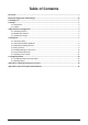
Table of Contents Foreword .................................................................................................................................................... I Important Safeguards and Warnings .................................................................................................... III 1 Packing List ........................................................................................................................................... 1 2 Design .............................
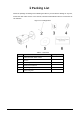
1 Packing List Check the package according to the following checklist. If you find device damage or any loss, contact the after-sales service. In the manual, "thermal network bullet camera" is referred to as "the Camera." Figure 1-1 Package items Table 1-1 Checklist No.
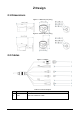
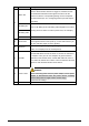
2 Design 2.1 Dimensions Figure 2-1 Model A (mm [inch]) Figure 2-2 Model B (mm [inch]) 2.2 Cables Figure 2-3 Cables Table 2-1 Ports description No. Port Description 1 LAN Connects to Ethernet cable.
No. Port Description Alarm IN1 Inputs signals from an alarm detection device such as a smoke detector. When smoke detector is triggered, it makes sounds and meanwhile transmits alarm signals to Camera for the Camera to start the corresponding linkage such as Snapshot and Send Email (see "5.1 Configuring Alarm Input and Output" for details). 2 ALARM_NO Connect ALARM_NO and ALARM_COM altogether to an alarm sending device to deliver an alarm (alarm voice, for example). ALARM_COM GND Ground terminal.
3 Web Interface Configuration For detailed camera operation on web interface, see Thermal Hybrid Camera_Web Operation Manual. 3.1 Initializing Camera Initialize your Camera and set the user password when you are logging in for the first time or after you have restored your camera to default settings. Initialize the Camera by ConfigTool or through web. This section takes web for example. Ensure your Camera IP address (192.168.1.108 by default) and your PC IP address are in the same network segment.
Click Next. Step 4 In the Online Upgrade interface, decide whether to do auto check for updates. After selecting the auto check, the newest version information will be displayed in Setting > System > Upgrade and Setting > Information > Version. You can also enable auto check in Setting > System > Upgrade. Figure 3-2 Online upgrade Step 5 Click Save. 3.2 Modifying IP Address Modify Camera IP address and ensure it is fitted to the actual network segment to get the Camera access network.
Step 3 Configure TCP/IP parameters. See Table 3-2. Table 3-2 TCP/IP parameters Parameter Description Host Name Give your Camera a name (TPCDome, for example) to help other people, (a router operator, for example), know the Camera information such as camera shape—dome thermal camera. IP Address, Subnet Mask and Default Gateway Enter the three item values according to the actual network segment.
4 Installation DANGER Before installation, make sure the power adapter is disconnected from the power source. Installing Camera with power on might result in serious injury. 4.1 Selecting Cables Power Cord To extend power cord you have received, evaluate the distance you want to extend and select the appropriate cord diameter. Hard copper cord is recommended. Table 4-1 Power cord Extension Distance [m (ft.)] Cord Diameter (mm) 10 (32.81) 0.9 15 (49.21) 1.1 20 (65.62) 1.3 25 (82.02) 1.5 30 (98.
4.2 Selecting Installation Methods Figure 4-1 Model A Table 4-2 Description No. Description No. Description 1 Ceiling mount 2 Wall mount 3 Pole mount 4 Corner mount Figure 4-2 Model B Table 4-3 Description No. Description No. Description 1 Wall mount 2 Pole mount 3 Corner mount — — For model B, the space between its antenna and the wall (or ceiling) should be no less than 3 cm.
4.3 (Optional) Installing SD Card Figure 4-3 Installing SD card Table 4-4 Tool and components No. Description No. Description No. Description 1 Cross screwdriver 2 SD card slot 3 Reset button 4.
Figure 4-5 Cable tray (through the pedestal side) 4.
4.6 Connecting Cable Ports Refer to "2.2 Cables" and connect each cable port to corresponding cables. Then use the insulting tape to seal each port to prevent water leakage. 4.
5 Configuring Alarm 5.1 Configuring Alarm Input and Output Add an alarm detection device, such as a smoke alarm device to your Camera to receive signals. For those signals, you can set camera linked measures such as Record, Send Email and Snapshot. You can also add an alarm sending device, such as a speaker to your Camera to warn suspicious people. Step 1 Connect alarm detection device to alarm input port of I/O cable. Step 2 Connect alarm sending device to alarm output port of I/O cable.
5.2 Working Theory Alarm input: When input signal is 3.3V or idle, the Camera collects logic "1"; when input signal is grounded, the Camera collects logic "0." Figure 5-2 Alarm input Alarm output: Port ALARM_OUT and ALARM_COM form a switch to provide alarm output. Normally the switch is off, and the switch will be on when there is an alarm output.
Appendix 1 Lightning and Surge Protection This series camera adopts TVS lightning protection technology. It can effectively prevent damages from various pulse signals below 6000V, such as sudden lightning and surge. While maintaining your local electrical safety code, you still need to take necessary precaution measures when installing the Camera in the outdoor environment. The distance between the signal transmission cable and high-voltage device (or high-voltage cable) shall be at least 50 meters.
Appendix 2 Cybersecurity Recommendations Cybersecurity is more than just a buzzword: it’s something that pertains to every device that is connected to the internet. IP video surveillance is not immune to cyber risks, but taking basic steps toward protecting and strengthening networks and networked appliances will make them less susceptible to attacks. Below are some tips and recommendations on how to create a more secured security system.
6. 7. 8. 9. 10. 11. 12. 13. 14. We suggest you to change default HTTP and other service ports into any set of numbers between 1024~65535, reducing the risk of outsiders being able to guess which ports you are using. Enable HTTPS We suggest you to enable HTTPS, so that you visit Web service through a secure communication channel. Enable Whitelist We suggest you to enable whitelist function to prevent everyone, except those with specified IP addresses, from accessing the system.
suggested to use VLAN, network GAP and other technologies to partition the network, so as to achieve the network isolation effect. Establish the 802.1x access authentication system to reduce the risk of unauthorized access to private networks. It is recommended that you enable your device's firewall or blacklist and whitelist feature to reduce the risk that your device might be attacked.