
Installation Manual
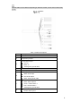
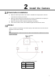


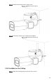
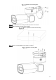
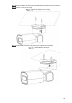
Table Of Contents
- Regulatory Information
- Foreword
- Important Safeguards and Warnings
- 1 Structure
- 2 Install the Camera
- Appendix 1 Thunder-Proof and Surge Protection
- Appendix 2 RS-485 Cable
- Appendix 3 Relationship between Cable Diameter (12V DC) and Transmission Distance
- Appendix 4 Wire Gauge Reference Sheet
- Appendix 5 Cybersecurity Recommendations

4
Camera cables can be different depending on different models, and the actual cables shall
prevail.
Cables
Table 1-4 Cable descriptions
No. Description
1
FC connector
2 DC power input port
3
24V AC power input.
Red: V+
Black: V–
Yellow-green: ground cable
4
RS-485: Yellow: A+, Orange: B–
5 Video output port
6
Ethernet port:
White: audio input
Red: audio output
Black: audio ground cable
7
Blue: alarm output 1
Black: alarm output 2
Green: contact switch 1
Pink: contact switch 2
Yellow-green: ground cable
8
Red: alarm input 1
Brown: alarm input 2